Chapter 10 PCI Controller
10-72
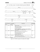
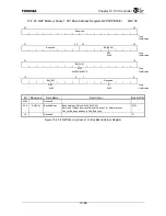
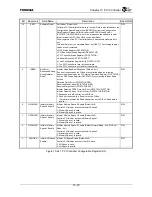
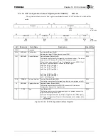
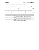
Bit Mnemonic Field
Name
Description
Read/Write
10
SRST
Software Reset
Soft Reset (Default: 0x0)
Performs PCI Controller software reset control. Data is also reloaded to the
Configuration Space Register from EEPROM or from the Configuration
Data Register. Please set this bit after the EEPROM Load End bit
(PCICSTATUS.E2PDONE) is set. Also, please use the software to clear
this bit at least four PCI Bus Clock cycles after Reset.
Other registers of the PCI Controller cannot be accessed while this bit is
set.
This bit differs from the Hardware Reset bit (HRST). The following register
values are not initialized.
•
G2P Status Register (G2PSTATUS)
•
PCI Bus Arbiter Status Register (PBASTATUS)
•
PCI Controller Status Register (PCICSTATUS)
•
Software Reset bit (PCICCFG.SRST)
•
Load Configuration Register bit (PCICCFG.LCFG)
1: The PCI Controller is reset by the software.
0: The PCI Controller is not reset by the software.
R/W
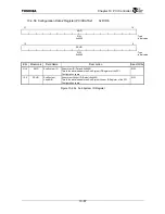
9 IRBER
Bus Error
Response Setting
During Initiator
Read
Initiator Read Bus Error Response (Default: 0x1)
Bus error responses on the G-Bus are controlled when the following
phenomena indicated by the PCI Status, Command Register (PICSTATUS)
and the G2P Status Register (G2PSTATUS) occur during initiator Read
access.
Detected Parity Error (PCISTATUS.DPE)
Received Master Abort (PCISTATUS.RMA)
Received Target Abort (PCISTATUS.RTA)
Initiator Detected TRDY Time Out Error (G2PSTATUS.IDTTOE)
Initiator Detected Retry Time Out Error (G2PSTATUS.IDRTOE)
1: Responds with a Bus error on the G-Bus.
0: Does not respond with a Bus error on the G-Bus.
(Normally terminates the Read transaction on the G-Bus. Read data is
invalid.)
R/W
8 G2PM0EN
Initiator Memory
Space 0 Enable
Initiator Memory Space 0 Enable (Default: 0x0)
Controls PCI initiator access to Memory Space 0.
1: Memory Space 0 is valid.
0: Memory Space 0 is invalid.
R/W
7 G2PM1EN
Initiator Memory
Space 1 Enable
Initiator Memory Space 1 Enable (Default: 0x0)
Controls PCI initiator access to Memory Space 1.
1: Memory Space 1 is valid.
0: Memory Space 1 is invalid.
R/W
6 G2PM2EN
Initiator Memory
Space 2 Enable
Initiator Memory Space 2 Enable (Default: Normal Mode: 0x0; PCI Boot
Mode: 0x1)
Controls PCI initiator access to Memory Space 2.
1: Memory Space 2 is valid.
0: Memory Space 2 is invalid.
R/W
5 G2PIOEN
Initiator I/O Space
Enable
Initiator I/O Space Enable (Default: 0x0)
Controls PCI initiator access to the I/O Space..
1: I/O Space is valid.
0: I/O Space is invalid.
R/W
Figure 10.4.41 PCI Controller Configuration Register (2/3)
Summary of Contents for TX49 TMPR4937
Page 1: ...64 Bit TX System RISC TX49 Family TMPR4937 Rev 2 0 ...
Page 4: ......
Page 13: ...Table of Contents ix TMPR4937 Revision History 1 ...
Page 14: ...Table of Contents x ...
Page 15: ...Handling Precautions ...
Page 16: ......
Page 18: ...1 Using Toshiba Semiconductors Safely 1 2 ...
Page 40: ...3 General Safety Precautions and Usage Considerations 3 18 ...
Page 42: ...4 Precautions and Usage Considerations 4 2 ...
Page 43: ...TMPR4937 2005 3 Rev 2 0 ...
Page 44: ......
Page 52: ...Chapter 1 Overview and Features 1 6 ...
Page 156: ...Chapter 7 External Bus Controller 7 56 ...
Page 491: ...Chapter 16 Removed 16 1 16 Removed ...
Page 492: ...Chapter 16 Removed 16 2 ...
Page 493: ...Chapter 17 Removed 17 1 17 Removed ...
Page 494: ...Chapter 17 Removed 17 2 ...
Page 495: ...Chapter 18 Removed 18 1 18 Removed ...
Page 496: ...Chapter 18 Removed 18 2 ...
Page 497: ...Chapter 19 Removed 19 1 19 Removed ...
Page 498: ...Chapter 19 Removed 19 2 ...
Page 506: ...Chapter 20 Extended EJTAG Interface 20 8 ...
Page 530: ...Chapter 22 Pinout and Package Information 22 10 ...
Page 542: ...Chapter 24 Parts Number when Ordering 24 2 ...


