Chapter 15 Interrupt Controller
15-7
15.3.5 Interrupt
notification
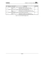
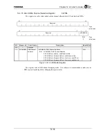
When the interrupt with the highest priority is selected, then the interrupt factor is reported to the
Interrupt Current Status Register (IRCS) and an interrupt is reported to the TX49/H3 core.
The TX49/H3 core distinguishes interrupt factors using the IP field (IP[7:2]) of the Cause Register.
The interrupt notification from the Interrupt Controller is reflected in the IP[2] bit. The Interrupt
Handler uses the IP[2] bit to judge whether or not there are interrupts from this Interrupt Controller and
uses the Interrupt Current Status Register (IRCS) to determine the interrupt cause.
The Interrupt Factor field (IRCS.CAUSE) value is reflected in the remaining bits of the IP field.
Since bit IP[7] is also being used for notification of TX49/H3 CPU core internal timer interrupts, the
contents specified by IP[7] differ according to whether internal timer interrupts are set to valid
(TINTDIS=0) or invalid (TINTDIS=1), as indicated Table 15.3.3.
TINTDIS is the value that is set from DATA[7] at the timing when the RESET* signal is deasserted.
See the explanation “3.3 Configuration Signals” for more information.
Table 15.3.3 Interrupt Notification to IP[7:2] of the CP0 Cause Register
TINTDIS IP[7]
IP[6:3]
IP[2]
0
(Internal Timer Interrupts: Valid)
Internal Timer
Interrupt Notification
IRCS.CAUSE[3:0] IRCS.IF
1
(Internal Timer Interrupts: Invalid)
IRCS.CAUSE[4:0] IRCS.IF
15.3.6 Clearing interrupt requests
Interrupt requests are cleared according to the following process.
•
When the detection mode is set to the High level or Low level:
Operation is performed to deassert the request of a source that is asserting an interrupt request.
•
When the detection mode is set to Rising edge or Falling edge
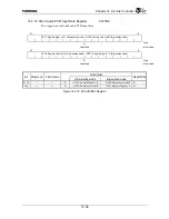
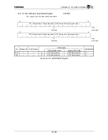
Edge detection requests are cleared by first specifying the interrupt source of the interrupt request
to be cleared in the Edge Detection Clear Source field (EDCS0 or EDCS1) of the Interrupt Edge
Detection Clear Register (IREDC) then writing the resulting value when the corresponding Edge
Detection Clear Enable bit (EDCE0 or EDCE1) is set to “1.”
Summary of Contents for TX49 TMPR4937
Page 1: ...64 Bit TX System RISC TX49 Family TMPR4937 Rev 2 0 ...
Page 4: ......
Page 13: ...Table of Contents ix TMPR4937 Revision History 1 ...
Page 14: ...Table of Contents x ...
Page 15: ...Handling Precautions ...
Page 16: ......
Page 18: ...1 Using Toshiba Semiconductors Safely 1 2 ...
Page 40: ...3 General Safety Precautions and Usage Considerations 3 18 ...
Page 42: ...4 Precautions and Usage Considerations 4 2 ...
Page 43: ...TMPR4937 2005 3 Rev 2 0 ...
Page 44: ......
Page 52: ...Chapter 1 Overview and Features 1 6 ...
Page 156: ...Chapter 7 External Bus Controller 7 56 ...
Page 491: ...Chapter 16 Removed 16 1 16 Removed ...
Page 492: ...Chapter 16 Removed 16 2 ...
Page 493: ...Chapter 17 Removed 17 1 17 Removed ...
Page 494: ...Chapter 17 Removed 17 2 ...
Page 495: ...Chapter 18 Removed 18 1 18 Removed ...
Page 496: ...Chapter 18 Removed 18 2 ...
Page 497: ...Chapter 19 Removed 19 1 19 Removed ...
Page 498: ...Chapter 19 Removed 19 2 ...
Page 506: ...Chapter 20 Extended EJTAG Interface 20 8 ...
Page 530: ...Chapter 22 Pinout and Package Information 22 10 ...
Page 542: ...Chapter 24 Parts Number when Ordering 24 2 ...

