Chapter 3 Signals
3-9
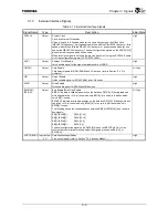
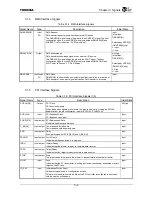
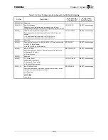
3.1.13 Initialization
Signal
Table 3.1.13 Initialization Signal
Signal Name
Type
Description
Initial State
RESET
*
Input
Reset
Reset signal.
Input
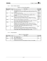
3.1.14 Test
Signals
Table 3.1.14 Test Signals
Signal Name
Type
Description
Initial State
TEST[4:0]
*
Input
PU
Test Mode Setting
Test pins. These pins must be left open or fixed to High.
TEST[1]
*
may be used when debugging the system. Toshiba recommends that your
board design enable the pin to be driven low after the TX4937 is mounted on the PC
board. Contact Toshiba technical staff for more information on the TEST[1]
*
functions.
Input
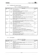
3.1.15 Power
Supply
Pins
Table 3.1.15 Power Supply Pins
Signal Name
Type
Description
Initial State
PLL1VDD_A,
PLL2VDD_A
⎯
PLL
Power
Pins
PLL analog power supply pins.
PLL1VDD_A = 1.5 V. PLL2VDD_A = 1.5 V.
⎯
PLL1VSS_A,
PLL2VSS_A
⎯
PLL Ground Pins
PLL analog ground pins.
PLL1VSS_A = 0 V. PLL2VSS_A = 0 V.
⎯
VccInt
⎯
Internal Power Pins
Digital power supply pins for internal logic. VccInt = 1.5 V.
⎯
VccIO
⎯
I/O
Power
Pins
Digital power supply pins for input/output pins. VccIO = 3.3 V.
⎯
Vss
⎯
Ground
Pins
Digital ground pins. Vss = 0 V.
⎯
Summary of Contents for TX49 TMPR4937
Page 1: ...64 Bit TX System RISC TX49 Family TMPR4937 Rev 2 0 ...
Page 4: ......
Page 13: ...Table of Contents ix TMPR4937 Revision History 1 ...
Page 14: ...Table of Contents x ...
Page 15: ...Handling Precautions ...
Page 16: ......
Page 18: ...1 Using Toshiba Semiconductors Safely 1 2 ...
Page 40: ...3 General Safety Precautions and Usage Considerations 3 18 ...
Page 42: ...4 Precautions and Usage Considerations 4 2 ...
Page 43: ...TMPR4937 2005 3 Rev 2 0 ...
Page 44: ......
Page 52: ...Chapter 1 Overview and Features 1 6 ...
Page 156: ...Chapter 7 External Bus Controller 7 56 ...
Page 491: ...Chapter 16 Removed 16 1 16 Removed ...
Page 492: ...Chapter 16 Removed 16 2 ...
Page 493: ...Chapter 17 Removed 17 1 17 Removed ...
Page 494: ...Chapter 17 Removed 17 2 ...
Page 495: ...Chapter 18 Removed 18 1 18 Removed ...
Page 496: ...Chapter 18 Removed 18 2 ...
Page 497: ...Chapter 19 Removed 19 1 19 Removed ...
Page 498: ...Chapter 19 Removed 19 2 ...
Page 506: ...Chapter 20 Extended EJTAG Interface 20 8 ...
Page 530: ...Chapter 22 Pinout and Package Information 22 10 ...
Page 542: ...Chapter 24 Parts Number when Ordering 24 2 ...

