background image

TOSHIBA 


21 

Other Option Modules 

There are a number of other optional modules that can be ordered 
for the 1700 Series UPS system.  Table 3 shows the available option 
modules.  For information about options not listed here contact 
Toshiba’s UPS Marketing Department at (800) 231-1412 or by e-mail 
at toshibaups@tic.toshiba.com. 

Table 3 

Option Modules 

Part No. 

Description 

Input 

Voltage 

Output 

Voltage 

UF1-IO-0XX-6BG 

Dual Transformer Module 

208V 

240/120V 

UF1-IO-0XX-6AA 

Single Isolation 
Transformer Module 

120V 120V 

UF1-IO-0XX-6EE 

Dual Transformer Module 

230V 

230V 

The XX in the part number is replaced by the kVA rating of the system (i.e. 2.4kVA = 024)


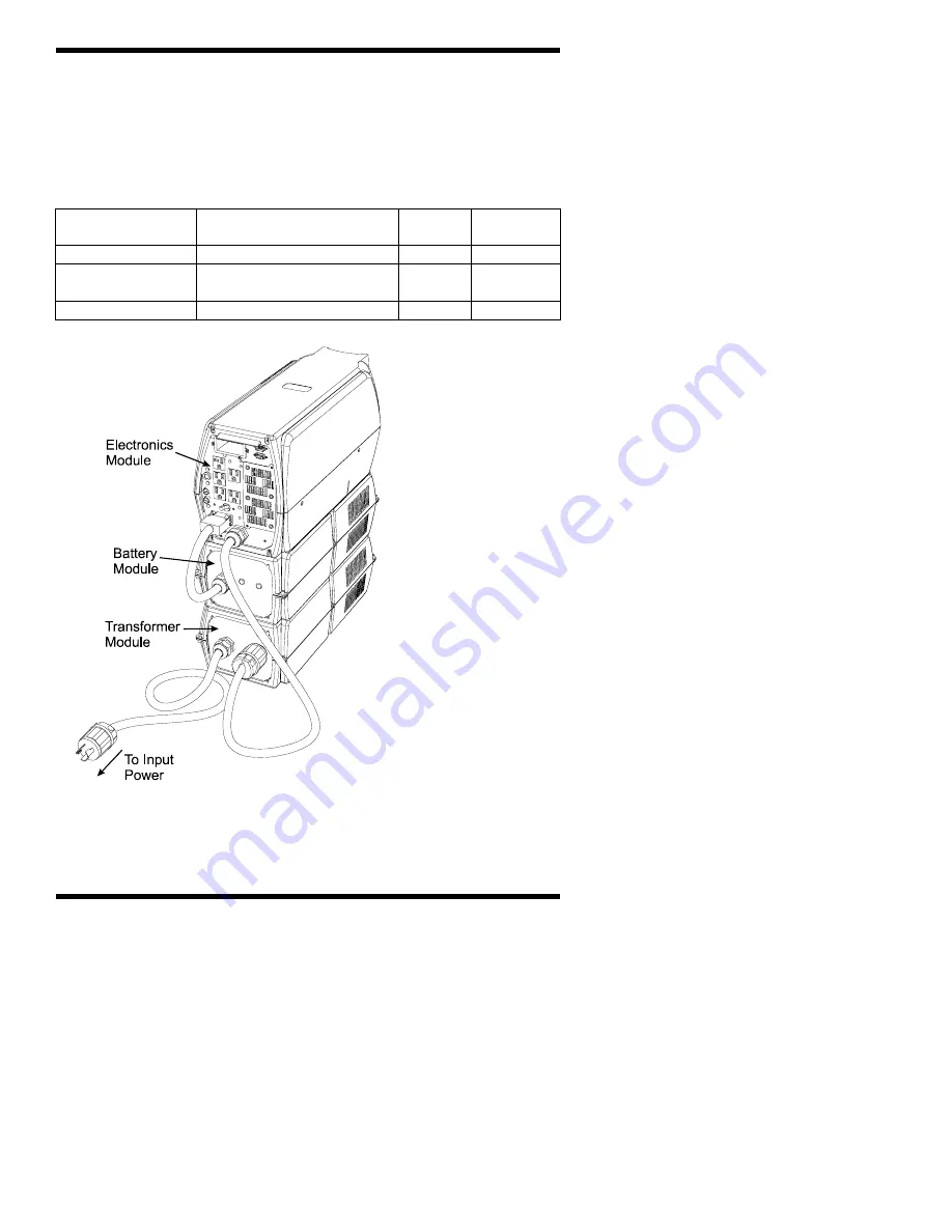
Figure 6 shows the 

standard 1700 series 
UPS with an optional 
input isolation 

transformer module 

(UF1-IO-024-6AA).  

Installation of the input 

transformer requires the 

input power cord from 

the electronics module 

to be plugged into the 

transformer module.  

The transformer power 

cord is plugged into the 

power source.  This is an 

example of how the option 

modules work.  An instruction 

sheet is included with each 

module that shows how to 

connect each particular module. 


Figure 6 

Isolation Transformer Module 

www 

. ElectricalPartManuals 

. com

Summary of Contents for UF1A1A015C6

Page 1: ...TOSHIBA 1 TOSHIBA User Manual Uninterruptible Power System 1700 Series Single Phase 1 5 2 0 2 4 kVA w w w E l e c t r i c a l P a r t M a n u a l s c o m ...

Page 2: ...TOSHIBA 2 w w w E l e c t r i c a l P a r t M a n u a l s c o m ...

Page 3: ...ional Corporation s UPS Division and any statements contained herein do not create new warranties or modify the existing warranty Any electrical or mechanical modifications to this equipment without prior written consent of Toshiba International Corporation will void all warranties and may void UL CUL listing Unauthorized modifications also can result in personal injury death or destruction of the...

Page 4: ...6 Battery Backup Time 16 Load Shed Function 16 Battery Recharge Time 16 Battery Check Function 17 The Function Control Button 17 Fixed Frequency Mode 20 Adding Additional Battery Modules 20 Other Option Modules 21 Communication Interface 22 Remote Contacts 22 RS 232C 22 Option Card Slot 22 Troubleshooting 22 Warning Fault Modes 22 Warnings 23 Faults 26 Storage of UPS Equipment 29 Disposal 29 Preve...

Page 5: ... CAUTION Other warning symbols may appear along with the Danger and Caution symbol and are used to specify special hazards These warnings describe particular areas where special care and or procedures are required in order to prevent serious injury and possible death 1 Electrical warnings The electrical warning symbol is a lightning bolt mark enclosed in a triangle The electrical warning symbol is...

Page 6: ...to use the proper model unit CAUTION Misuse of this equipment could result in human injury and equipment damage In no event will Toshiba Corporation be responsible or liable for either indirect or consequential damage or injury that may result from the use of this equipment DANGER Do not dispose of the battery module in a fire The batteries inside may explode CAUTION Do not open or mutilate the ba...

Page 7: ...t la sécurit ATTENTION Une batterie peut présenter un risque de choc électrique de brûlure par transfert d énergie ATTENTION Pour le remplacement utiliser le même nombre de batteries du modèle suivant ATTENTION L élimination des batteries est réglementée Consulter les codes locaux à cet effet w w w E l e c t r i c a l P a r t M a n u a l s c o m ...

Page 8: ...t are subject to high humidity 5 Do not install the UPS in a location that will cause direct sunlight to shine on the unit 6 Do not install the UPS in areas that are subject to contamination such as high levels of airborne dust metal particles or flammable gas 7 Avoid installation near sources of electrical noise Always make sure that the unit earth ground is intact to prevent electrical shock and...

Page 9: ... output 4 Do not use the UPS to provide power to motors that require high starting current or that require a long starting time such as vacuum cleaners and machine tools unless appropriate sizing is done by a Toshiba applications engineer or other qualified personnel 5 Do not insert metal objects or combustible materials in the unit s ventilation slots 6 Do not place hang or paste any objects on t...

Page 10: ...wo modules that make up the standard unit If additional battery modules are being installed with the standard unit see page 20 For all other option modules see page 21 Note No more than three modules should be stacked on top of each other for any configuration Figure 2 Battery Module Layout w w w E l e c t r i c a l P a r t M a n u a l s c o m ...

Page 11: ... unlock the units lift up on the top module and slide it back This will release the interlock figure 3 Step 3 Connect the input power cord figure 4 to the AC power source If no AC power source is available go to step 5 Step 4 Switch the input breaker to the on position figure 1 page 9 Step 5 Plug the battery cord coming from the battery pack into the blue battery plug located on the back of the el...

Page 12: ...om batteries If not already done switch the input breaker on figure 1 page 9 If the AC Input LED is lit proceed on to Starting when AC power is available If the LED is not lit there is no AC power available If the unit is to be started when AC power is not available proceed to Starting on DC power Starting When AC Power is Available If the system is being started with AC input power the system is ...

Page 13: ...wn Option 1 The first option is to place the UPS into bypass mode Bypass mode means that if there is AC power available the UPS will route power directly from the input source to the connected loads without any conditioning The UPS inverter is off during this state but the attached loads do not lose power during the transition To place the UPS into bypass mode switch the RUN STOP switch to the STO...

Page 14: ...sound for 1 second at 10 second intervals Alarm is off LED State On Line On AC Input On 20 to 100 On see note 1 On Line On Battery On Backup On 60 to 100 On see note 2 AC Input On 20 to 100 On see note 1 Display State UPS Display Status and Operating Condition Operation Mode Normal Battery Backup Bypass w w w E l e c t r i c a l P a r t M a n u a l s c o m ...

Page 15: ...he load increases until that full percentage is reached For example if the unit is loaded to 40 of maximum output power the 20 and 40 LEDs will be lit If another small load is added increasing the load to 45 the 60 LED will begin to blink If a little bit more load is added so that the total load becomes 50 the 60 LED will blink faster This will continue until enough load is added to equal 60 of th...

Page 16: ...1 Backup Time UPS Model With 1 Battery Module Full Load Half Load With 2 Battery Modules Full Load Half Load 1500 VA 13 min 35 min 35 min 90 min 2000 VA 10 min 25 min 25 min 60 min 2400 VA 7 min 20 min 23 min 50 min Times given are approximate and will vary depending on the age of the batteries the ambient temperature the number of previous discharges and the type of load Load Shed Function The 17...

Page 17: ...ressing the Function Control button will cause the UPS to check the batteries again If the batteries pass the test the unit will return to normal operation If the batteries fail the test again they should be allowed to charge see Table 2 Battery Recharge Time and the test should be performed again If the batteries continue to fail the tests the battery module should be replaced It is important to ...

Page 18: ...hed Function page 16 for an explanation of load shedding To accept this option press and hold the Function control button For the next option go to step B A 1 The UPS comes from the factory set so the load shed receptacles function for the full battery backup time Pressing the Function Control button will change the setting for the load shed level The LEDs on the right side of the display will lig...

Page 19: ...rt time after which the UPS will exit programming mode and return to bypass operation To return the system to normal operation switch the RUN STOP switch back to the RUN position C Reset Battery Installed Date This should be done whenever a new battery pack is installed Press the function control button The unit is now ready to reset the battery installed date This is indicated by the Battery LED ...

Page 20: ...amming mode does not change the bypass setting in the case of a fixed frequency mode unit Adding an Additional Battery Module Figure 5 shows the standard unit with the expansion battery module added The expansion battery module differs from the standard battery module in that it has an additional battery input connector on the back To install an expansion battery module follow these steps 1 Unplug...

Page 21: ...e 120V 120V UF1 IO 0XX 6EE Dual Transformer Module 230V 230V The XX in the part number is replaced by the kVA rating of the system i e 2 4kVA 024 Figure 6 shows the standard 1700 series UPS with an optional input isolation transformer module UF1 IO 024 6AA Installation of the input transformer requires the input power cord from the electronics module to be plugged into the transformer module The t...

Page 22: ...e Communication Option User Manual for a more detailed explanation of this option Troubleshooting Warnings and Faults are those abnormal conditions that can occur and could cause the unit to stop normal operation These conditions are detected by the protective circuitry in the unit The UPS Warning Fault lamp will light red when a warning or fault occurs Troubleshooting involves monitoring the LED ...

Page 23: ...ing the room temperature to exceed 104 F 40 C a blocked vent or direct sunlight on the unit The unit will transfer to bypass until the temperature is reduced Alarm State Alarm will sound for 1 second at 5 second intervals Alarm will sound for 1 2 second at 1 second intervals Alarm will sound for 1 second at 15 second intervals LED State On Line On Warning Fault Flash Battery On Backup Flash 20 40 ...

Page 24: ...e exhausted the unit will shutdown or switch to bypass according to selected settings Alarm State Alarm will sound for 1 second at 15 second intervals Alarm will sound for 1 2 second at 10 second intervals Alarm will sound for 2 1 2 second beeps at 10 second intervals LED State On Line On AC Input On Warning Fault Flash Battery Flash 20 to 100 On according to current amount of connected load On Li...

Page 25: ...C Input On Warning Fault Flash 150 Flash Display State Warnings cont d Warning Input Frequency Regulation On Line mode see note 3 Output Overload Flashing LED LED lit continuously Note 1 If the unit is operating in Bypass mode and an input undervoltage condition occurs the Warning Fault LED will flash along with the 20 LED The unit will shutdown The AC Input LED may also be on if some AC voltage i...

Page 26: ... according to settings Batteries must charge before backup power will be available For charging times see page 16 This fault indicates an internal problem with the UPS Contact your Toshiba UPS service representative at 1 800 231 1412 Alarm State Alarm will sound for 1 2 second at 1 2 second intervals Continuous alarm Alarm will sound for 1 2 second at 1 2 second intervals LED On Line On AC Input O...

Page 27: ... 1 800 231 1412 Alarm State Alarm will sound for 1 2 second at 1 2 second intervals LED State AC Input On Warning Fault On 40 On AC Input On Warning Fault On 60 On AC Input On Warning Fault On 80 On Display State Faults Fault DC Bus Over Voltage DC Bus Voltage Imbalance Output Under Voltage w w w E l e c t r i c a l P a r t M a n u a l s c o m ...

Page 28: ...resentative at 1 800 231 1412 Alarm State Alarm will sound for 1 2 second at 1 2 second intervals LED State AC Input On Warning Fault On 100 On AC Input On Warning Fault On 150 On Display State Faults Fault Output Over Voltage System Over Heat Flashing LED LED lit continuously w w w E l e c t r i c a l P a r t M a n u a l s c o m ...

Page 29: ...es to need recharging more frequently Recharging requirements during storage Recharging the batteries requires that the battery module be connected to the UPS and the UPS must have AC input power available The UPS can be in either the on line or bypass mode See Starting the UPS page 12 and Battery Recharge Time page 18 1 If stored in an ambient temperature less than 20 C 68 F recharge the batterie...

Page 30: ...ventilation openings Schedule authorized Toshiba service centers to perform internal parts inspections annually or call a Toshiba UPS service representative at 1 800 231 1412 CAUTION Proper maintenance of the battery system of this unit is essential to the safety and reliability of the UPS system Parts Replacement The following list shows intervals for periodic maintenance and replacement of certa...

Page 31: ...r one minute 150 for 30 seconds Output Crest factor 2 5 at full load Type 12V flame retardant sealed lead acid Battery backup time fully charged 0 7 power factor 25 C 77 F 13 minutes at full load 7 minutes at full load Battery Configuration 2 strings in parallel 4 batteries per string Operating temperature 0 to 40 C 32 to 104 F Altitude Up to 1000m 3000 ft above sea level Environment Efficiency 86...

Page 32: ...aph above refers to the temperature inside the UPS There will typically be a 5 C difference between the internal and external temperature The 10 hysteresis shown is to ensure that the unit will not oscillate between fan speeds When the output power reaches a level that requires the fan speed to increase the load will have to be reduced 10 below that level before the fan speed will return to the lo...

Page 33: ...se of the breaker depending on the applied load The two lines shown on the graph represent the upper and lower limits of the breaker response The response of a particular breaker could fall anywhere between these two lines If the load capacity of the breaker is exceeded the breaker will trip shutting down both the UPS and the attached loads If the breaker s capacity is not exceeded the unit will c...

Page 34: ...being used the time the unit can operate in parallel mode is limited However the time will be longer than that available when the unit is operating on battery power alone The point when the UPS will enter parallel mode will vary depending on the output load The following graph shows the various stages based on full output load and 75 output load As shown by the graph the lower the output load the ...

Page 35: ...N STOP switch is in the STOP bypass position the unit will start in the on line mode for 1 second before switching to bypass mode If the input voltage is out of range the UPS will turn off the output after 1 second rather than switching to bypass The overvoltage and undervoltage limits can be turned off by the user if desired see Function Control Button section 3 Programming mode part B page 18 If...

Page 36: ...sformer UF1 IO 015 6EE 230V input 230V output transformer module UF1 BC 087 48V battery module UF1 EBC 087 Extended runtime 48V battery module UF1 IO 024 6BG 208V input 240V 120V output transformer module UF1 IO 024 6AA 120V input isolation transformer module UF1A1A024C6 2400VA Electronics Module UF1 IO 024 6EE 230V input 230V output transformer module UF1 BC 087 48V battery module UF1 EBC 087 Ext...

Page 37: ...le Module Weight Shipping Weight Model No Pounds Kilograms Pounds Kilograms UF1A1A015C6 26 12 31 14 UF1A1A015C6T 46 21 51 23 UF1A1A024C6 30 14 35 16 UF1A1A024C6T 50 23 55 25 UF1 BC 087 51 23 56 25 w w w E l e c t r i c a l P a r t M a n u a l s c o m ...

Page 38: ...nutes 110 2 Maximum number of full charge discharge cycles 5 minutes 130 VALVE REGUALATED LEAD ACID VRLA BATTERIES FOT TOSHIBA UPS INSTALLATION AND MAINTENANCE CONDITIONS 3 Storage While UPS is in transit or storage it must always be in suitable temperature see condition 1 4 External Batteries Parallel battery string applications must be approved by TIC in writing 5 Idle Batteries User must rechar...

Page 39: ...ing conditions were met then the BATTERY capacity will be tested in accordance with the performance test guidelines IEEE Std 450 If the BATTERY fails to deliver 70 of its rated capacity it shall be deemed defective and be replaced Either float or cyclic service will be used to determine the warranty credit as per published Battery Diagnostic Document The typical credit applied will be as in the fo...

Page 40: ...TOSHIBA 40 Notes w w w E l e c t r i c a l P a r t M a n u a l s c o m ...

Page 41: ...TOSHIBA 41 Notes w w w E l e c t r i c a l P a r t M a n u a l s c o m ...

Page 42: ...SHIBA 42 TOSHIBA TOSHIBA INTERNATIONAL CORPORATION INDUSTRIAL DIVISION 13131 West Little York Rd Houston Texas 77041 Tel 800 231 1412 Fax 713 466 8773 w w w E l e c t r i c a l P a r t M a n u a l s c o m ...

Reviews: