28
Q9 Plus ASD Installation and Operation Manual
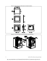
LED/LCD Screen Installation Note
When installing the LED/LCD display unit of the EOI, ensure that the left side of the display is inserted
first with the top and bottom catches (see Phillips screws at underside of display) securely in place. This
ensures the proper alignment and electrical connection of the CNX connector of the LED/LCD display
unit board. Gently hold the display in place while securing the Phillips mounting screw.
If improperly seated, the periphery of the LED/LCD display unit will not be flush with the EOI surface
and the unit will not function properly.
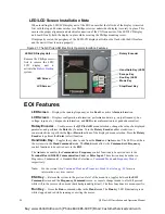
Figure 21. The Q9 Plus ASD Electronic Operator Interface Features.
EOI Features
LED Screen
— Displays the running frequency, active
Fault
, or active
Alarm
information.
LCD Screen
— Displays configuration information, performance data (e.g., output frequency, bus
voltage, torque, etc.), diagnostic information, and
LED
screen information in expanded normal text.
Rotary Encoder
— Used to access the
Q9 Plus ASD
menu selections, change the value of a displayed
parameter, and performs the
Enter
key function. Turn the
Rotary Encoder
either clockwise or
counterclockwise to perform the
Up
or
Down
functions of the displayed menu selection. Press the
Rotary
Encoder
to perform the
Enter
(select) function.
Hand/Auto Key
— Toggles the system to and from the
Hand
and
Auto
modes. The LED is on when
the system is in the
Hand Command
mode. The
Hand
mode allows the
Command
and
Frequency
control functions to be carried out via the
EOI
.
The
Auto
mode enables the
Command
and
Frequency
control functions to be carried out via the
Terminal Board
,
RS485
,
Communication Card
,
or
Pulse Input
. The selection may be made via
Program
Fundamental
Standard Mode Selection
Command Mode
and
Frequency Mode 1
,
respectively.
Note:
See the section titled
Command Mode and Frequency Mode Control on pg. 36
for more
information on system control.
ESC Key
— Returns the system to the previous level of the menu tree, toggles between the
EOI
Command
screen and the
Frequency Command
screen, or cancels changes made to a field if pressed
while still in the reverse video mode (dark background/light text). The three functions are menu-specific.
Run Key
— Issues the
Run
command while in the
Hand
mode. The
Run
key LED illuminates green
while stopped and red while running or exciting the motor.
Remove the Phillips screw
first to remove the LED/
LCD display unit to
activate the
Battery Backup
system.
LED/LCD Display Unit
Rotary Encoder
LCD Screen
Hand/Auto Key (LED)
Escape Key
Run Key (LED)
Mode Key
Stop/Reset Key
LED Screen
Buy: www.ValinOnline.com | Phone 844-385-3099 | Email: CustomerService@valin.com

