background image

10

1

Features

„

Main features

Power saving ventilation

The cost of cooling and heating is reduced thanks to 
the unit efficiently retrieving thermal energy (outdoor 
air load) which has been lost during ordinary 
ventilation.

Space saving

Significant reduction of outdoor air load and the ability 
to retrieve thermal energy enable the production of 
smaller air conditioning devices.

Humidity control

When cooling, highly humid outdoor air is conditioned 
to near the humidity of the dehumidified (cooled) indoor 
air before being supplied. 
When heating, moisture from the return air is 
transferred to the dry outdoor air before the outdoor air 
is supplied.

Comfortable ventilation

Ventilation without big changes in temperature is 
realized.
In addition, stable ventilation is possible even in an air 
tight room due to simultaneous air intake and 
expulsion.

Sound insulation

Air trunks and heat exchange elements provide sound 
insulation.
They reduce the incoming of outdoor noise and the 
outward flow of sounds indoor and help keep the office 
or shop, and their surroundings quiet.

Easy installation

The linear air supplying/exhausting method enables 
simple design and installation.
Inverted installation is possible and only one inspection 
slot is required for two units.
A complete inspection is possible through a single 
inspection slot.

Other

The filter has excellent dust filtering performance 
(mass spectrometry 82%).
The air volume can be switched between Extra High 
and High.

The ventilation balance of air supplying and air 
exhausting can be changed.
The filter inspection display function calculates the total 
running time and prompts you through the remote 
controller to inspect the filter.
The cold mode function automatically makes the air 
supplying motor run intermittently when the outdoor air 
temperature is -10°C or lower.
The timer function allows you to set the unit to start/
stop operation at the specified time.
The separately sold central controller enables central 
control of 128 groups.
The separately sold wired remote controller enables 
group operation control of up to 8 units.
The unit can operate in cooperation with an air-
conditioner (SMMS series, DI/SDI series).

„

About ventilation modes

The unit has three ventilation modes.

• Heat exchange mode

Exchanging heat between the outdoor air and return 
air and making the temperature and humidity of the 
outdoor air closer to those of the return air before 
supplying it.

• Bypass mode

Outdoor air is taken into a room as it is. This mode is 
mainly used in spring and summer.

• Automatic mode
1. For an Air to Air Heat Exchanger system

The heat exchange mode and the bypass mode are 
automatically switched between following the 
information from the return air and outdoor air 
temperature sensors in the unit.

2. For an Air to Air Heat Exchanger system linked with 

air conditioners
The heat exchange mode and the bypass mode are 
automatically switched between depending on the 
operation status of the air conditioner (cooling, 
heating, dry, fan, or temperature setting) and the 
information from the return air and outdoor air 
temperature sensors in the unit.

CAUTION

If the outdoor air temperature becomes about to 15°C or 
less in [Automatic mode] or [Bypass mode], the system 
will automatically start to run in [Heat exchange mode] 
regardless of the mode setting to prevent condensation 
in the Air to Air Heat Exchanger.
* The indication of the ventilation mode setting does not 

change.

Summary of Contents for VN-M1000HE

Page 1: ...Air to Air Heat Exchanger SERVICE MANUAL FILE No A10 021 Concealed microcomputer control type Model name VN M150HE VN M250HE VN M350HE VN M500HE VN M650HE VN M800HE VN M1000HE ...

Page 2: ... Functions Including Circuit Configuration 28 8 Air to Air Heat Exchanger Unit and Air Conditioning System 37 9 Failure Diagnosis 44 10 Exchanging and Assembling the Main Components 51 11 Owner s Manual 63 12 Installation Manual 91 13 How to replace the PC board for service on the Air to Air Heat Exchanger 139 14 Exploded Diagram Parts List 143 ...

Page 3: ...in such matters by an individual or individuals who have been trained and is thus thoroughly acquainted with the knowledge related to this work The qualified installer who is allowed to work at heights has been trained in matters relating to working at heights with the Air to Air Heat Exchanger made by Toshiba Carrier Corporation or alternatively he or she has been instructed in such matters by an...

Page 4: ...electricians and from heat Work done at heights 50 cm or more Helmets for use in industry Transportation of heavy objects Shoes with additional protective toe cap Indication Explanation DANGER Indicates contents assumed that an imminent danger causing a death or serious injury of the repair engineers and the third parties when an incorrect work has been executed WARNING Indicates possibilities ass...

Page 5: ...all remote electric power supplies before servicing WARNING Moving parts Do not operate unit with inspection cover removed Stop the unit before the servicing CAUTION High temperature parts You might get burned when removing this cover WARNING ELECTRICAL SHOCK HAZARD Disconnect all remote electric power supplies before servicing WARNING Moving parts Do not operate unit with inspection cover removed...

Page 6: ... on by marking out of service near the circuit breaker for instance until qualified service person arrives Continuing to use the Air to Air Heat Exchanger in the trouble status may cause mechanical problems to escalate or result in electric shocks or other failure Electric shock hazard When you access inside of the electrical control cover to repair electric parts wait for about five minutes after...

Page 7: ...d gloves to provide protection from electric shock Otherwise you may receive an electric shock Use a hand track or forklift to carry the unit When carrying it by human power have four persons or more otherwise you may strain your back When transporting the Air to Air Heat Exchanger wear shoes with protective toe caps protective gloves and other protective clothing When transporting the Air to Air ...

Page 8: ...d installer 1 or qualified service person 1 is allowed to relocate the Air to Air Heat Exchanger It is dangerous for the Air to Air Heat Exchanger to be relocated by an unqualified individual since a fire electric shocks injury water leakage noise and or vibration may result Check the following items after reinstallation 1 The earth wire is correctly connected 2 The power cord is not caught in the...

Page 9: ...ocate the Air to Air Heat Exchanger It is dangerous for the Air to Air Heat Exchanger to be relocated by an unqualified individual since a fire electric shocks injury water leakage noise and or vibration may result 1 Refer to the Definition of Qualified Installer or Qualified Service Person ...

Page 10: ...der Toshiba Carrier UK Ltd Porsham Close Belliver Industrial Estate PLYMOUTH Devon PL6 7DB United Kingdom Hereby declares that the machinery described below Generic Denomination Air to Air Heat Exchanger Model type VN M150HE VN M250HE VN M350HE VN M500HE VN M650HE VN M800HE VN M1000HE Commercial name TOSHIBA Air to Air Heat Exchanger Complies with the provisions of the Machinery Directive Directiv...

Page 11: ...ng time and prompts you through the remote controller to inspect the filter The cold mode function automatically makes the air supplying motor run intermittently when the outdoor air temperature is 10 C or lower The timer function allows you to set the unit to start stop operation at the specified time The separately sold central controller enables central control of 128 groups The separately sold...

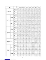
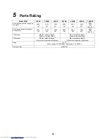
Page 12: ... 49 0 74 0 94 1 30 1 85 2 69 Low 50Hz 0 20 0 20 0 25 0 26 0 38 0 37 0 59 0 60 1 25 1 30 1 31 1 27 1 62 1 57 60Hz 0 20 0 25 0 43 0 66 0 95 1 52 1 87 Bypass Mode Extra high 50Hz 0 31 0 33 0 58 0 61 0 76 0 76 0 99 1 00 1 25 1 30 1 67 1 63 2 47 2 46 60Hz 0 36 0 60 0 99 1 20 1 40 2 03 2 84 High 50Hz 0 27 0 28 0 47 0 49 0 62 0 61 0 81 0 81 1 14 1 13 1 57 1 50 2 31 2 28 60Hz 0 28 0 49 0 74 0 94 1 30 1 85...

Page 13: ...20 0 22 0 21 0 22 0 27 0 29 0 26 0 29 0 31 0 32 5 33 5 35 0 34 0 35 5 60Hz 20 21 23 5 24 5 29 5 32 5 33 5 Bypass Mode Extra high 50Hz 26 0 28 0 29 5 30 0 34 0 35 0 32 5 34 0 34 0 36 0 37 0 38 5 39 5 40 5 60Hz 27 5 31 5 35 5 33 5 35 5 38 41 5 High 50Hz 24 0 25 5 25 0 27 0 30 0 32 0 29 5 31 0 33 0 34 0 35 5 37 0 38 5 40 0 60Hz 24 5 25 29 5 29 34 35 39 Low 50Hz 20 0 22 0 21 0 22 0 27 0 29 0 26 0 29 0...

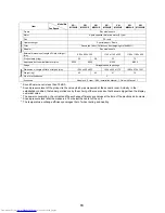
Page 14: ... Construction Frame Zinc steel sheets Motor 4 pole capacitor dielectric motor E type Fan PP resin Heat exchanger Special paper Resin Filter Nonwoven fabric Collection effect weighing method 82 Adapter Zinc steel sheets External dimensions Length x Width x Height mm 900 x 900 x 290 1140 x 1140 x 350 1189 x 1189 x 400 Product weight kg 36 38 53 70 Applicable duct nominal diameter mm Ø100 Ø150 Ø200 Ø...

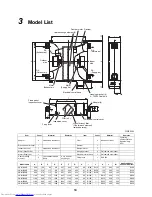
Page 15: ... VN M250HE 900 670 115 810 957 900 454 97 Ø145 Ø158 162 290 145 Ø150 VN M350HE 900 670 115 810 957 900 454 97 Ø145 Ø158 162 290 145 Ø150 VN M500HE 1140 800 170 1050 1197 1140 454 80 Ø195 Ø212 350 175 Ø200 VN M650HE 1140 800 170 1050 1197 1140 454 80 Ø195 Ø212 350 175 Ø200 VN M800HE 1189 800 195 1099 1246 1189 454 85 Ø245 Ø262 400 200 Ø250 VN M1000HE 1189 800 195 1099 1246 1189 454 85 Ø245 Ø262 400...

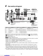
Page 16: ... B A 2 OFF CN040 1 4 3 2 2 34 1 2 1 3 CN041 OFF ON SW703 ON CN106 1 2 t TOA t 1 7 43F22 3 43F12 5 2 3 43F11 5 1 3 5 5 43F21 1 3 2 C C P01 CN701 8 43F12 FM1 M 1 M 1 M FM2 7 7 7 CN704 RY705 RY702 3 5 1 3 CN760 5 2 1 3 4 RY709 RY708 RY710 6 5 1 3 9 7 5 6 CN702 43F21 8 8 8 43F11 43F22 DAM 3 1 2 4 5 TB3 4 CN705 2 1 3 CN706 1 5 2 1 5 2 2 B A Power supply for the Air to Air Heat Exchanger 220 240V 50Hz 2...

Page 17: ...or exhaust air fan motor 450V 1ȝF 450V 1ȝF 450V 3ȝF 450V 3ȝF 450V 3ȝF 450V 5ȝF 450V 10ȝF 5ȝF x 2 TOA sensor Ø5 size lead wire length 900mm vinyl tube Blue Ø5 size lead wire length 1040mm vinyl tube Blue TRA sensor Ø5 size lead wire length 1010mm non migratory tube Black Ø5 size lead wire length 1270mm non migratory tube Black Relay LY 1F Rated voltage AC220V 240V Rated load 10A AC220V Damper motor...

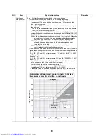
Page 18: ... Control The display on the remote controller remains Bypass regardless of the ventilation mode in actual operation When operation starts in Bypass mode the Heat Exchange mode is maintained for three minutes if the state before stop is Heat Exchange mode cold mode control 1 Air to Air Heat Exchanger system 1 Automatic mode control One of the following three zones is selected by the TOA and TRA sen...

Page 19: ...e OA Outdoor Air C RA Return Air C Cooling zone Heating zone Bypass Y N Y N N Y N Y N Y N Y Fan zone Heat Exchange Continue current ventilation mode Y N Y N Y N Y N N Y Start operation Y N OA 24 C RA 24 C RA 20 C OA 20 C Automatic ventilation determination in air conditioning linkage RA OA detection DN EC Invalid 0002 DN EC Valid when stopped 0001 Other than Fan mode and OA RA 3 C RA 18 C and RA 1...

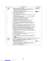
Page 20: ...ation mode and set temperature before stop 0002 Invalid The zone is determined by the automatic ventilation mode control in the Air to Air Heat Exchanger system 2 The Bypass condition at the time of automatic ventilation mode control in the Air to Air Heat Exchanger system linked with air conditioners excluding Fan mode Cooling zone RA OA 3 C and RA set temperature 2 C and OA RA 10 C 14 5 C and RA...

Page 21: ...oller is used The ventilation mode can be changed with CODE No DN EB of the DN setting CODE No DN EB 48 NO Item Specification outline Remarks 4 8 12 16 20 24 28 32 8 12 16 20 24 28 32 Heat Exchange Bypass Undefined zone OA Outdoor Air C RA Return Air C Maximum set temperature Heating zone Y N Y N N Y Cooling zone Heating zone Bypass Heat Exchange Start operation Automatic ventilation determination...

Page 22: ...is pressed when they are running and the system enters 24 hour ventilation mode 6 In the Air to Air Heat Exchanger system linked with air conditioners Air to Air Heat Exchangers stop if the VENT button is pressed when only the Air to Air Heat Exchangers are running or when both the Air to Air Heat Exchangers and air conditioners are running and the system enters 24 hour ventilation mode The settin...

Page 23: ...4 Nighttime heat purge operating conditions The nighttime heat purge monitoring operation start time specified in the DN setting 1 to 48 hours has passed Temperature monitoring operation is performed for five minutes Heat Exchange mode and nighttime heat purge operation starts if the following conditions are met RA 0A 3 C and RA set temperature 2 C and OA RA 10 C 14 5 C 5 During nighttime heat pur...

Page 24: ...24 hour ventilation setting invalid Air to Air Heat Exchangers and air conditioners are stopped Air to Air Heat Exchanger system linked with air conditioners Nighttime heat purge setting valid Set time to start of monitoring operation between 1 and 48 hours Operation mode before stop Cooling or Drying mode As monitoring operation start time 1 to 48 hours have passed 48 hours have passed since star...

Page 25: ...r it stops for 60 minutes and runs for five minutes The setting of the exhausting fan can be changed with CODE No DN 4D of the DN setting 0000 Exhausting fan runs factory default 0001 Exhausting fan stops CODE No DN 4D NO Item Specification outline Remarks Zone Zone criterion Bypass mode permitted zone Zone A OA RA 10 C 12 5 C Zone A Zone B OA 10 C or OA RA 36 C Zone B Zone C OA 15 C or OA RA 41 C...

Page 26: ...n the Air to Air Heat Exchanger system linked with air conditioners the cumulative time of the nighttime heat purge operation is not counted 2 In the Air to Air Heat Exchanger system the cumulative operating time of the exhausting fan of the Air to Air Heat Exchanger header unit is the representative of the group In the Air to Air Heat Exchanger system the cumulative operating time of 24 hour vent...

Page 27: ...ture is below 10 C 0003 Contact is on only when SA fan Supplying fan is running Contact is off when 24 hour ventilation is stopped intermittently so do not connect an auxiliary fan 0004 Contact is on only when EA fan Exhausting fan is running Contact is off when 24 hour ventilation is stopped intermittently so do not connect an auxiliary fan CODE No DN ED External output terminal block 1 2 11 Elec...

Page 28: ...rnal device overrides the former 0001 The Air to Air Heat Exchanger starts together with the starting of an external device Use the remote controller to stop operation 0002 The Air to Air Heat Exchanger stops together with the stopping of an external device Use the remote controller to start operation Operation signals DN 4E CODE No DN 4E Remote ON OFF adapter NRB 1HE sold separately No 1 of the s...

Page 29: ...edule timer when in weekly timer mode Air to Air Heat Exchanger 1 Function setting Key switch Damper motor Supplying fan motor Exhausting fan motor Power supply circuit Fan motor relay circuit Fan motor relay circuit Driver TOA sensor Driving Damper Abnormal Bypass mode Remote controller invalid Low High Bypass mode Heat Exchange mode Start Stop AC synchronous signal input circuit BUS communicatio...

Page 30: ...low Remote controller communication LED D504 green Connectors for the external input CN705 red DC12V Pulse Static changeover switch SW701 Damper motor CN760 white DC12V Connectors for the external input CN706 white Connectors for the external output CN704 white Supply air fan motor CN701 white Exhaust air fan motor CN702 red SW702 SW703 Power supply CN67 black AC100V Changeover switch for the indo...

Page 31: ...tion mode is Cooling or Heating in the Air to Air Heat Exchanger system linked with air conditioners the ventilation mode is fixed to Heat Exchange If the operation mode is Fan in the Air to Air Heat Exchanger system linked with air conditioners the ventilation mode is fixed to Bypass Procedure Operation 1 When the button is pushed for 4 seconds or more TEST is displayed in the display section and...

Page 32: ...e of the equipment may be caused Limit using this function within several minutes How to operate Short circuit CHK pin CN71 on the P C board How to clear Open CHK pin While the system is operating it stops once but automatically returns to operation after several minutes For the detailed positions of CHK pin CN71 on P C board refer to the P C board MCC 1615 Short circuit of CHK pin Fan motor H Ven...

Page 33: ...Prohibited OFF Allowed 3 Ventilation fan speed change input Ventilation fan speed change input ON LOW OFF HIGH 4 Ventilation mode change input Ventilation mode change input ON Bypass OFF Heat Exchange 5 Start Stop input Start Stop input pulse static input changed by No 1 of DIP SW701 OFF Static default ON Pulse External input DC12V 24V CN706 1 DC12V COM 2 Start Stop input Start Stop input pulse st...

Page 34: ...he line system address is always 31 The indoor unit address is between 1 and 64 The address is specified with No 1 to No 4 of SW702 and with No 1 and No 2 of SW703 2 Each time you press left side of the button the unit No of the Air to Air Heat Exchangers in the group are displayed successively Only the fan of the selected Air to Air Heat Exchanger starts running 3 Press the temperature button to ...

Page 35: ...der unit System equipped with the Air to Air Heat Exchanger and air conditioners 47 24 hour nighttime heat purge Fan speed ventilation setting 0000 Always LOW 0001 Fan speed ventilation before the operation is stopped 24 hour nighttime heat purge Fan speed ventilation setting 0000 Always LOW Adjusting this setting is necessary for all the Air to Air Heat Exchangers in the group 48 Imbalanced Fan s...

Page 36: ...at Exchanger only EA Changing the ventilation mode 0001 Bypass mode 0002 Heat Exchange mode 0003 Automatic mode Compatible with systems without a remote controller and RBC AMT32E RBC AMS41E 0003 Automatic mode 1 EB Changing the ventilation Fan speed 0002 High 0003 Low 0004 Imbalanced High may be Extra High Compatible with systems without a remote controller and RBC AMT32E RBC AMS41E 0002 High 1 EC...

Page 37: ...the normal display Indoor unit data Air to Air Heat Exchanger CODE No Data name 02 Indoor unit Return air temperature TRA F0 Microcomputer cumulative energized hours x 100h F2 Supply air fan cumulative energized hours x 100h F3 Filter cumulative hours x1 h FA Indoor unit outdoor air temperature TOA Model Code 10 Factory default value of EEPROM installed on the service circuit board Capacity of the...

Page 38: ...it VN M OO HE 4 Old Air to Air Heat Exchanger unit VN OO TE VN 1K TAE VN 1K TBE TCC LINK line Remote controller NRC 01HE Pattern 1 Pattern 2 Not on the assumption of connection with an Air to Air Heat Exchanger unit or via general purpose device interface 1 3 Possible 2 3 Possible When a unit not yet compatible with Air to Air Heat Exchange is connected the ventilation mode and fan speed cannot be...

Page 39: ...38 Pattern 3 Pattern 4 Pattern 5 Pattern 6 1 4 Not Possible 2 4 Not Possible RC 1 4 Not Possible RC 2 4 Not Possible ...

Page 40: ...7 Pattern 8 Pattern 9 1 2 3 Possible 1 3 2 Possible 1 3 2 Possible When linking a unit compatible with Air to Air Heat Exchange to one not yet compatible you need to set a compatible unit as the group header unit ...

Page 41: ...door unit type Cassette type Duct type Ceiling type High wall type 4 way air discharge type Compact 4 way air discharge type 2 way air discharge type 1 way air discharge type Duct type Built in type Slim duct type Development No Series No 2 4 2 4 4 4 4 4 4 Compatibility Indoor unit type Floor type Floor standing type Fresh air intake type Cabinet type Concealed type Console type Development No Ser...

Page 42: ...unit is not yet compatible with the Air to Air Heat Exchanger unit The linkage operation is possible but changing the ventilation mode and fan speed is not possible Will be possible if the DN setting is changed Indoor unit type Cassette type Duct type Ceiling type High wall type Flexi type 4 way air discharge type Compact 4 way air discharge type Duct type Built in type Slim duct type Development ...

Page 43: ...ne system address of an Air to Air Heat Exchanger unit is always 31 The indoor unit address of an Air to Air Heat Exchanger unit needs to be manually specified in No 1 to No 4 of SW702 and in No 1 and No 2 of SW703 The setting of the smallest address applies to the remote controller display The group address of an Air to Air Heat Exchanger unit does not need to be specified Remote controller Air c...

Page 44: ...ess of an Air to Air Heat Exchanger unit is always 31 The indoor unit address of an Air to Air Heat Exchanger unit needs to be manually specified in No 1 to No 4 of SW702 and in No 1 and No 2 of SW703 The setting of the smallest address applies to the remote controller display The group address of an Air to Air Heat Exchanger unit does not need to be specified Remote controller Air conditioner gro...

Page 45: ...rcuit is open Replace the motor with a new one Connection A connection is loose Connect firmly Electric board Motor connector Motor The motor bearing is locked The motor coil or temperature fuse is broken Replace the motor with a new one Fan rotation The fan is not rotating Remove any obstacles Capacitor The capacitor is not working properly Replace the capacitor with a new one An abnormal sound i...

Page 46: ...en circuit or short circuit of the outdoor air temperature sensor TOA was detected F18 Return air temperature sensor TRA error Open circuit or short circuit of the return air temperature sensor TRA was detected F29 Indoor unit or other P C board error EEPROM error Another error may have been detected L03 Duplicate header indoor units There are two or more header units in the group L08 Indoor group...

Page 47: ...tus 1 When pushing and buttons at the same time for 4 seconds or more the following display appears If Service check is displayed the mode enters in the trouble history mode 01 Order of error history is displayed in CODE No window Check code is displayed in CHECK window Air to Air Heat Exchanger address in which an error occurred is displayed in Unit No Unit No of Air to Air Heat Exchanger is 31 O...

Page 48: ...d in memory The error history can be accessed regardless of whether the Air to Air Heat Exchanger is in operation or shut down 1 Press and hold the and buttons simultaneously for at least four seconds 2 lights up and CODE No 01 is displayed 3 If there is an error history when a group number is selected blinking the unit No and the latest error history information are displayed alternately 4 To che...

Page 49: ...it is shut down with alarm while follower indoor units continue operating Check remote controller settings Check remote controller board E18 Indoor Error in communication between indoor header and follower units Stop of corresponding unit only Periodic communication between indoor header and follower units cannot be maintained Check remote controller wiring Check indoor power supply wiring Check P...

Page 50: ...rol device Check for defects in central control communication line Check termination resistance setting C06 TCC LINK TCC Link central control device reception error Continued operation Central control device is unable to receive a signal Check for defects in the central control device Check for defects in central control communication line Check termination resistance setting Check power supply fo...

Page 51: ...2 0 3 0 40 50 6 0 70 1 0 0 10 15 5 0 20 100 150 50 200 0 8 0 9 0 100 20 30 1 0 2 0 3 0 40 50 10 20 0 Resistance k Characteristic 1 Characteristic 2 Temperature C Temperature C Return air temperature sensor TRA Outdoor air temperature sensor TOA Resistance k 10 C or less Resistance k 10 C or more ...

Page 52: ... HEAT EXCHANGER then pull it out Note A single heat exchange element HEAT EXCHANGER weighs 2 4 kg there are two elements Be careful not to drop it 3 Element rail RAIL 1 3 3 Remove the two screws M4 6 that fix the element rail RAIL to pull the rail out 4 Foam cover COVER FOAM 1 4 4 Slide the foam cover COVER FOAM to the center of the product to pull it out Lever LEVER LID Machine screws M4 12 Inspe...

Page 53: ...the connector of motor Note The connector of the supply motor MOTOR SUPPLY is white The connector of the exhaust motor MOTOR EXHAUST is black 7 Cover COVER WIRE 1 2 7 7 Remove the four screws M4 6 that fix the cover COVER WIRE then remove the cover No Component Procedure Note Screws M4 6 Screws M4 6 Electrical control cover COVER PC BOARD Push this part with your nail to disconnect the connector E...

Page 54: ...do not lose the key and washer left in the motor shaft No Component Procedure Note Supply motor MOTOR SUPPLY Exhaust motor MOTOR EXHAUST Release Bigclamp CLAMP 4 Screws M5 8 used 4 Screws M4 6 used 4 Machine screws with captive washer M8 16 used 150 350 type 500 1000 type Machine screws with captive washer M8 16 500 1000 type Screws M4 6 500 1000 type Screws M5 8 150 350 type Machine screws with c...

Page 55: ...OLDER MOTOR Bell mouth BELL MOUTH 1 6 8 13 13 Remove the four screws M4 6 that fix the motor holder HOLDER MOTOR and bell mouth BELL MOUTH then pull the four holders out Note The bell mouth BELL MOUTH of the 800 1000 type comes with the motor holder HOLDER MOTOR No Component Procedure Note 800 1000 type Hexagon head screws M8 16 Motor holder HOLDER MOTOR 150 650 type Pan head screws M5 8 Motor hol...

Page 56: ... There is one on the inspection cover LID SERVICE and one on the Lid holder HOLDER LID 14 Chain CHAIN 15 16 16 Separate the chain CHAIN from the coupling COUPLING 15 Lid holder HOLDER LID 1 15 17 17 Remove the four screws M4 6 that fix the lid holder HOLDER LID then remove the holder Two screws per location there are two locations No Component Procedure Note Exhaust casing CASE ASSY EXHAUST Inspec...

Page 57: ...e the damper motor holder without removing the screw completely 18 Damper motor MOTOR LOUVER 1 2 19 22 21 Remove the connector CONNECTOR 9 from the damper motor MOTOR LOUVER 22 Remove the two screws that fix the damper motor MOTOR LOUVER then remove it 19 Damper DAMPER 1 2 19 23 23 Remove the damper DAMPER from the damper motor holder STAY DAMPER MOTOR Remove the damper motor MOTOR LOUVER then rem...

Page 58: ...l the connectors through the cord bushes 25 Remove the two tapping screws SCREW TAPPING then remove the electrical control base LID ELECTRIC PARTS No Component Procedure Note Connectors Cord bush Electrical control base LID ELECTRIC PARTS Tapping screws SCREW TAPPING Electrical control base LID ELECTRIC PARTS Electrical control box BOX ELECTRIC PARTS ...

Page 59: ...NECTOR 6 CONNECTOR 7 Remove the two screws that fix the power supply terminal block TERMINAL BLOCK 2P then remove the power supply terminal block 24 External terminal block TERMINAL BLOCK 5P 5 29 29 Pull out the fastening terminal of the connector CONNECTOR 5 Remove the two screws that fix the external terminal block TERMINAL BLOCK 5P then remove the external terminal block No Component Procedure ...

Page 60: ...t the cable tie then remove the connector of the sensor SENSOR TRA from the PC board PC BOARD Note When cutting the cable tie be careful not to cut the lead wire unintentionally Connector of TRA sensor SENSOR TRA CN105 Brown Connector of TOA sensor SENSOR TOA CN106 white 27 TOA sensor SENSOR TOA 1 2 5 32 33 33 Release the small clamp CLAMP and big clamp CLAMP that fix the TOA sensor SENSOR TOA the...

Page 61: ... firmly After inserting the connector pull it slightly to make sure it is firmly inserted 29 Connector 1 CONNECTOR 1 5 6 34 35 44 45 35 Pull out the fastening terminals of the power supply terminal block TERMINAL BLOCK 2P relay RELAY LY 1F and capacitor CAPACITOR Remove the connector connecting connector 1 and 2 CONNECTOR 1 and 2 30 Connector 2 CONNECTOR 2 5 34 36 45 36 Pull out the fastening term...

Page 62: ...t the fastening terminal of the power supply terminal block TERMINAL BLOCK 2P Pull out the fastening terminal of the relay RELAY LY 1F 35 Connector 7 CONNECTOR 7 5 28 34 41 45 41 Pull out the fastening terminal of the power supply terminal block TERMINAL BLOCK 2P Remove the connector of the PC board PC BOARD 36 Connector 8 CONNECTOR 8 5 30 34 42 42 Pull out the fastening terminal of the communicat...

Page 63: ...7 8 c 1 2 3 4 5 6 7 8 d 1 2 3 4 5 6 7 8 For exhaust motor Relay a 4321F 1 3 5 7 Empty CONNECTOR 2 Red CONNECTOR 3 White CONNECTOR 4 Light blue 2 4 6 8 Empty Empty Empty CONNECTOR 4 Brown Relay b 4322F 1 3 5 7 Empty CONNECTOR 1 Brown CONNECTOR 6 Red CONNECTOR 4 Light blue 2 4 6 8 CONNECTOR 3 White Empty Empty CONNECTOR 4 Pink For supply motor Relay c 4311F 1 3 5 7 Empty CONNECTOR 2 White CONNECTOR ...

Page 64: ...eat Exchanger Please read this owner s manual carefully before using your Air to Air Heat Exchanger Obtain the Owner s manual and Installation manual from constructor or dealer Request to constructor or dealer Please clearly explain the contents of the Owner s manual and hand over it This appliance is not intended for use by person including children with reduced physical sensory or mental capabil...

Page 65: ...roughly acquainted with the knowledge related to this work The qualified installer who is allowed to work at heights has been trained in matters relating to working at heights with the Air to Air Heat Exchangers made by Toshiba Carrier Corporation or alternatively he or she has been instructed in such matters by an individual or individuals who have been trained and is thus thoroughly acquainted w...

Page 66: ...it with inspection cover removed Stop the unit before the servicing CAUTION High temperature parts You might get burned when removing this cover WARNING ELECTRICAL SHOCK HAZARD Disconnect all remote electric power supplies before servicing WARNING Moving parts Do not operate unit with inspection cover removed Stop the unit before the servicing CAUTION High temperature parts You might get burned wh...

Page 67: ...rrectly Operation Before opening the electrical control cover or inspection cover of the Air to Air Heat Exchanger set the circuit breaker to the OFF position Failure to set the circuit breaker to the OFF position may result in electric shocks through contact with the interior parts Only a qualified installer 1 or qualified service person 1 is allowed to remove the electrical control cover or insp...

Page 68: ...such as preserving food precision instruments art objects breeding animals car vessel etc Do not touch any switches with wet finger otherwise you may get an electric shock If the Air to Air Heat Exchanger will not be used for a considerably long time turn off the main switch or the circuit breaker for safety Prevent any liquid from falling into the remote controller Do not spill juice water or any...

Page 69: ...king height 3 cartons can be stacked in this case This side up Do not step Handle with care Weight Do not roll Do not clamp Other cautions Description CAUTION Injury possibility Don t handle with packing band or may get injured in case of broken band Stacking notice In case that cardboard boxes protrude out of pallet when stacking Lay a 10 mm thick plywood over the pallet 2 cartons 79 kg ...

Page 70: ...their surroundings quiet About ventilation modes The unit has three ventilation modes Heat exchange mode Exchanging heat between the outdoor and indoor air and making the temperature and humidity of the outdoor air closer to those of the indoor air before supplying it Bypass mode Outdoor air is taken into a room as it is This mode is mainly used in spring and summer Automatic mode 1 For an Air to ...

Page 71: ...de down when the unit is installed upside down Outdoor air intake duct Pipe hood Hanging bolt Supply air duct SA Supply air RA Return air Indoor supply opening Supply Exhaust Air grille Room intake opening Supply Exhaust Air grille Return air intake duct Heat insulation material Exhaust air duct EA Exhaust air OA Outdoor air ...

Page 72: ... Exchanger system linked with air conditioners The remote controller for the air conditioner or the Air to Air Heat Exchanger can be used to start stop the whole system The remote controller for the air conditioner or the Air to Air Heat Exchanger can be used to start stop the Air to Air Heat Exchanger separately However setting modifications are required for separate control Contact your dealer f...

Page 73: ...olling the air conditioners and the Air to Air Heat Exchangers together The central controller can be used to start stop the whole system It can also be used to start stop the Air to Air Heat Exchanger separately However setting modifications are required for separate control Contact your dealer for more information The central controller cannot be used to control the Ventilation fan speed or vent...

Page 74: ...VN M1000HE 1189 1189 400 VN M500HE 1140 1140 350 Inspection cover Heat exchange element two SA Supply air OA Outdoor air Filter Two for each element RA Return air EA Exhaust air Model No indication Electrical control cover B C A Indoor side Outdoor side SA Supply air RA Return air OA Outdoor air EA Exhaust air Heat exchange element two High efficiency filter One for each element sold separately Fi...

Page 75: ...d with air conditioners Push the button to turn on off the Air to Air Heat Exchanger Turning on off the air conditioner also turn on off the Air to Air Heat Exchanger No Air to Air Heat Exchanger is connected or separate operation of the Air to Air Heat Exchanger is not set if appears on the remote controller display after pushing the button 5 button Filter reset button Resets FILTER indication af...

Page 76: ...speed button Used to select the ventilation fan speed You can stop 24 hour ventilation temporarily by pressing and holding the button for 4 seconds while is displayed 14 button Ventilation mode button Used to select a ventilation mode 15 button Filter elevating button 1 This function is not available OPTION Remote controller sensor 1 Normally the temperature sensor of the indoor unit senses the te...

Page 77: ...splayed when setting the timer or other functions 2 Operation mode indicator 1 Indicates the operation mode selected 3 Error indicator Displayed when the protective device activates or an error occurs 4 Time indicator Indicates time concerning the timer Indicates a error code when an error occurs 5 Timer mode indicator Each time you press the button the indication changes as follows and no timer i...

Page 78: ... type only 18UNIT No indicator The number of the Air to Air Heat Exchanger selected using the UNIT button or that of the unit in which an error has occurred 19Central control indicator Displayed when a central control device such as a central controller is also used If the central control device prohibits the use of local remote controllers blinks when any of the or TEMP buttons are pressed and th...

Page 79: ... heat purge operation Displayed when the setting is activated 27 Ventilation on standby indicator Displayed while the Air to Air Heat Exchanger is on standby While this indicator is displayed the Air to Air Heat Exchanger is not in operation Displayed when the setting is activated 28 Ventilation indicator If the remote is used to control the Air to Air Heat Exchanger in the Air to Air Heat Exchang...

Page 80: ... used after a long period of disuse turn on the circuit breaker of the unit and air conditioners 12 hours or more before starting operation Operations 1 Push the buttons to start operation The operation lamp lights up REQUIREMENT Operation will be started when the heat exchange ventilation is in an Air to Air Heat Exchanger system linked with air conditioners 2 Push the button to select the ventil...

Page 81: ...fan speed When SA EA is selected the volume of the indoor air supply is larger than that of the outdoor air exhaustion Inflow of humidity and smells from the toilet and kitchen is reduced When SA EA is selected the volume of the outdoor air exhaustion is larger than that of the indoor air supply Outflow of smells and floating bacteria into a corridor or other places is reduced Consult your dealer ...

Page 82: ...cannot be changed during the nighttime heat purge operation Their indicators are not displayed The indicator stays lit while the operation is on standby or paused The nighttime heat purge operation cannot be activated if 24 hour ventilation is activated CAUTION The nighttime heat purge operation is not executed if the outdoor temperature becomes about 15 C or less to prevent condensation in the Ai...

Page 83: ...4 hours to 168 hours each time is pushed Example of indication on the remote controller 23 5 hours 1 34 hours 2 4 Push the button disappears the time indication is displayed and or flashes When using the ON timer all indications other than the time indication and turn off Cancelling the timer 1 Push the button The timer indicator disappears NOTE When using the Repeat OFF timer pressing the button ...

Page 84: ... 2 Press the button after cleaning the filter The FILTER RESET indicator disappears If the filter or heat exchange element is clogged the ventilation amount is reduced and ventilation effect will be deteriorated CAUTION Cleaning remote controller Use a dry cloth to wipe the remote controller Do not use a damp cloth on the remote controller Do not use a chemically treated duster for wiping or leave...

Page 85: ... 1 85 2 69 Low 50Hz 0 20 0 20 0 25 0 26 0 38 0 37 0 59 0 60 1 25 1 30 1 31 1 27 1 62 1 57 60Hz 0 20 0 25 0 43 0 66 0 95 1 52 1 87 Bypass Mode Extra high 50Hz 0 31 0 33 0 58 0 61 0 76 0 76 0 99 1 00 1 25 1 30 1 67 1 63 2 47 2 46 60Hz 0 36 0 60 0 99 1 20 1 40 2 03 2 84 High 50Hz 0 27 0 28 0 47 0 49 0 62 0 61 0 81 0 81 1 14 1 13 1 57 1 50 2 31 2 28 60Hz 0 28 0 49 0 74 0 94 1 30 1 85 2 69 Low 50Hz 0 2...

Page 86: ...0 21 0 22 0 27 0 29 0 26 0 29 0 31 0 32 5 33 5 35 0 34 0 35 5 60Hz 20 21 23 5 24 5 29 5 32 5 33 5 Bypass Mode Extra high 50Hz 26 0 28 0 29 5 30 0 34 0 35 0 32 5 34 0 34 0 36 0 37 0 38 5 39 5 40 5 60Hz 27 5 31 5 35 5 33 5 35 5 38 41 5 High 50Hz 24 0 25 5 25 0 27 0 30 0 32 0 29 5 31 0 33 0 34 0 35 5 37 0 38 5 40 0 60Hz 24 5 25 29 5 29 34 35 39 Low 50Hz 20 0 22 0 21 0 22 0 27 0 29 0 26 0 29 0 31 0 32...

Page 87: ...gth x Width x Height mm 900 x 900 x 290 1140 x 1140 x 350 1189 x 1189 x 400 Product weight kg 36 36 38 53 53 70 70 Applicable duct nominal diameter mm Ø100 Ø150 Ø200 Ø250 Item Model No Fan Speed VN M150HE VN M250HE VN M350HE VN M500HE VN M650HE VN M800HE VN M1000HE ...

Page 88: ...he time set has passed Consult your dealer for details The unit runs though the operation lamp does not turn on Does the or indicator appear on the display The nighttime heat purge operation or 24 hour ventilation is set to ON See page 79 for how to use the functions Consult your dealer to change the setting to OFF The unit starts running without any operation of the remote controller Has the unit...

Page 89: ...the remote controller The check code is only displayed during the operation If the display disappears operate the Air to Air Heat Exchanger according to the following Confirmation of error history for confirmation Unit No of the Air to Air Heat Exchanger is 31 When a trouble occurred on the Air to Air Heat Exchanger the trouble history can be confirmed with the following procedure The trouble hist...

Page 90: ...tional information please contact the municipal facility the shop dealer installer that sold the product or the producer X Country Y Name of Company responsible for WEEE The manufacturer reserves the right to change any product specifications without notice X Y Austria AIRCOND Klimaanlagen Handelsgesellshcaft m b H Petersgasse 45 A 8010 Graz Austria Belgium DOLPHIN NV Fotografi elaan 12 B 2610 Ant...

Page 91: ...YMOUTH Devon PL6 7DB United Kingdom Hereby declares that the machinery described below Generic Denomination Air to Air Heat Exchanger Model type VN M150HE VN M250HE VN M350HE VN M500HE VN M650HE VN M800HE VN M1000HE Commercial name TOSHIBA Air to Air Heat Exchanger Complies with the provisions of the Machinery Directive Directive 2006 42 EC and the regulations transposing into national law Must no...

Page 92: ...Air Heat Exchanger Please read this owner s manual carefully before using your Air to Air Heat Exchanger Obtain the Owner s manual and Installation manual from constructor or dealer Request to constructor or dealer Please clearly explain the contents of the Owner s manual and hand over it Read this Installation Manual thoroughly to fully understand everything about your Toshiba Air to Air Heat Exc...

Page 93: ... thus thoroughly acquainted with the knowledge related to this work The qualified installer who is allowed to work at heights has been trained in matters relating to working at heights with the Air to Air Heat Exchanger made by Toshiba Carrier Corporation or alternatively he or she has been instructed in such matters by an individual or individuals who have been trained and is thus thoroughly acqu...

Page 94: ...othing Electrical related work Gloves to provide protection for electricians and from heat Work done at heights 50 cm or more Helmets for use in industry Transportation of heavy objects Shoes with additional protective toe cap Warning indication Description WARNING ELECTRICAL SHOCK HAZARD Disconnect all remote electric power supplies before servicing WARNING Moving parts Do not operate unit with i...

Page 95: ...oach the work location before proceeding with the work Parts and other objects may fall from above possibly injuring a person below The Air to Air Heat Exchanger must be transported in stable condition In case an accident such as dropping of the unit occurs while transporting the Air to Air Heat Exchanger contact the dealer Do not move or repair any unit by yourself There is high voltage inside th...

Page 96: ...hese checks When there is some kind of trouble such as when an error display has appeared there is a smell of burning abnormal sounds are heard or water is leaking has occurred in the Air to Air Heat Exchanger do not touch the Air to Air Heat Exchanger yourself but set the circuit breaker to the OFF position and contact a qualified service person Take steps to ensure that the power will not be tur...

Page 97: ...er line and the connecting line with accuracy so the power source cover may not float If the installation of the electrical control cover is inappropriate the pin connection area is likely to cause a heat generation a fire and an electric shock due to dust or powder Do not use the unit at the other voltages than the rated one It could cause a fire or an electric shock Do not install the unit in lo...

Page 98: ...Usage Installation manual 1 Hand it to the customers CD ROM Owner s manual and Installation manual 1 For other languages that do not appear in this manual please refer to the enclosed CD ROM Owner s manual 1 Hand it to the customers Adapter 4 Connection parts for the duct Screw 16 24 Screws for attaching the adapter Model No A mm B mm C mm Weight kg Heat exchange element VN M150HE M250HE 900 900 2...

Page 99: ...e dewed or frosted To avoid this heating a low temp air B up to B is required so as to get C below the saturation curve before using the unit Refrain from the following duct installation works Do not install it near the water heater Do not use in bathrooms or food preparation areas or in similar condition place If the unit is used at the place of much soot and high humidity large amounts of oily s...

Page 100: ...hanger can be operated using this remote controller 5 Reference Diagram Outdoor air intake duct Pipe hood Hanging bolt Supply air duct SA Supply air RA Return air Inside supply opening Supply Exhaust Air grille Room intake opening Supply Exhaust Air grille Return air intake duct Heat insulation material Exhaust air duct EA Exhaust air OA Outdoor air ...

Page 101: ... 1140 454 80 Ø195 Ø212 350 175 Ø200 VN M800HE 1189 800 195 1099 1246 1189 454 85 Ø245 Ø262 400 200 Ø250 VN M1000HE 1189 800 195 1099 1246 1189 454 85 Ø245 Ø262 400 200 Ø250 D A B 25 L C C 200 E M 25 F G I K J H H SA Supply air RA Return air EA Exhaust air OA Outdoor air Indoor side Outdoor side Damper Damper motor Heat exchange element 2 Hanging bracket 4 4 13 X30 Oval hole Electrical control base...

Page 102: ...ially available vibration proof fixture when the unit is installed in a place where preventing vibration is necessary Leave a space of 450mm x 450mm or more for checking the filter heat exchanging element power source or motor Refer to Cautions for Installation for the location of the space required Cautions installing unit body upside down The hanging bracket does not need to be replaced The prin...

Page 103: ...tdoor ducts including outdoor air and exhaust air duct to prevent dewing Material Glass Wool Thickness 25mm See the figure below To pierce the metal duct through the metal lath or the wire lath or the metal plate of the wooden facility insulate electrically between the duct and the wall Refer to the laws and regulations of the country concerned and the technical standard It is recommended that an ...

Page 104: ...product Do not damage or scratch the conductive core and inner insulator of power and communication wires when peeling them Use the power and communication wire of specified thickness type and protective devices required Do not connect 220 240V power to the communication terminal blocks for control wiring Otherwise the system will fail REQUIREMENT For power supply wiring strictly conform to the Lo...

Page 105: ...p to 1000m 1 25 mm2 Up to 2000m 2 0 mm2 2 core non polarity 0 5 mm2 to 2 0 mm2 2 The length of the communication wire is the total length of the outdoor indoor transition wire and wire of the central control assuming that an interlocking system with the indoor unit or central control system is used To prevent noise use a 2 core shielded wire Remote controller wiring remote controller inter unit wi...

Page 106: ...B A 2 OFF CN040 1 4 3 2 2 34 1 2 1 3 CN041 OFF ON SW703 ON CN106 1 2 t TOA t 1 7 43F22 3 43F12 5 2 3 43F11 5 1 3 5 5 43F21 1 3 2 C C P01 CN701 8 43F12 FM1 M 1 M 1 M FM2 7 7 7 CN704 RY705 RY702 3 5 1 3 CN760 5 2 1 3 4 RY709 RY708 RY710 6 5 1 3 9 7 5 6 CN702 43F21 8 8 8 43F11 43F22 DAM 3 1 2 4 5 TB3 4 CN705 2 1 3 CN706 1 5 2 1 5 2 2 B A Power supply for the Air to Air Heat Exchanger 220 240V 50Hz 22...

Page 107: ...rminator SW301 No 1 100ȍ ON None OFF Changeover switch for the central control address SW703 No 3 Fix ON Auto OFF Changeover switch for the group address SW703 No 4 Header Individual ON Follower OFF Changeover switch for pulse static SW701 No 1 Pulse ON Level OFF Connectors for the external input Remote ON OFF adapter NRB 1HE sold separately No voltage a contact input Remote controller operation I...

Page 108: ...fix the wiring on the electrical control box using the accessory cord clamp Perform grounding work S R B A U1 U3 U2 U4 30 30 S N R L Communication wire terminal block Wiring for the central control U3 U4 Wiring for the remote controller A B Power supply terminal block R L S N External output terminal block 1 2 3 4 5 Operation output Common External damper output 3 4 Abnormal Bypass mode output 3 5...

Page 109: ...ing As the remote controller wire has non polarity there is no problem if connections to Air to Air Heat Exchanger terminal blocks A and B are reversed Wiring diagram For details of wiring installation of the remote controller refer to the Installation Manual enclosed to in the remote controller Exhaust air red connector Supply air white connector Blue lead wire High Factory default Cord clip REQU...

Page 110: ...ilable for RBC AMS41E Air to Air Heat Exchanger system linked with air conditioners The remote controller for the air conditioner or the Air to Air Heat Exchanger can be used to ON OFF the whole system The remote controller for the Air to Air Heat Exchanger NRC 01HE can be used to control the ventilation fan speed and ventilation mode of the Air to Air Heat Exchanger The remote controller for air ...

Page 111: ...able for RBC AMS41E Central control system When controlling the air conditioner and Air to Air Heat Exchanger together The central controller can be used to ON OFF the whole system It can also be used to ON OFF the Air to Air Heat Exchanger separately The central controller cannot be used to control the ventilation fan speed or ventilation mode of the Air to Air Heat Exchanger If three control dev...

Page 112: ...Header Individual ON Necessary Header ON 1unit Follower OFF the other units Settings of the header unit reflect the indications of the remote controller Not necessary Follower OFF all units Settings of the follower unit with the smallest indoor unit address number reflect the indication of the remote controller 4 Fix Automatic changeover of the central control address No 3 of SW703 Not necessary 5...

Page 113: ...he header unit reflect the indications of the remote controller Necessary Header Individual ON Necessary Header ON 1unit Follower OFF the other units Settings of the header unit reflect the indications of the remote controller Not necessary Follower OFF all units Settings of the follower unit with the smallest indoor unit address number reflect the indication of the remote controller 4 Fix Automat...

Page 114: ... 14 30 46 62 15 31 47 63 16 32 48 64 1 ON 2 3 4 1 ON 2 3 4 SW702 SW703 ON OFF Changing the group address Header Individual ON Follower OFF When the system equipped with the Air to Air Heat Exchanger s only is used set only one unit as the header unit When the system equipped with the Air to Air Heat Exchanger and air conditioners is used be sure to set all the Air to Air Heat Exchangers as followe...

Page 115: ...E The line system address is fixed as 31 for the Air to Air Heat Exchanger Air to Air Heat Exchanger system One Air to Air Heat Exchanger is used Changing the group address No 4 of SW703 Settings for changing the group address are necessary Select Header ON Factory default Follower When Header ON is selected Individual ON will be selected in this system Changing the indoor unit address No 1 to 4 o...

Page 116: ...nit address No 1 to 4 of SW702 No 1 and 2 of SW703 Settings for changing the indoor unit address are necessary Do not duplicate the value 1 to 64 Factory default 1 B L N L N L N A B A B A B U1 U3 U2 U4 A B U1 U3 U2 U4 A B U1 U3 U2 U4 For group control install remote controller inter unit wiring between the units Up to 8 units can be installed for group control Air to Air Heat Exchanger Power suppl...

Page 117: ...it Factory default OFF 100 ON 1 header unit only None OFF the other units For the settings of the central control address refer to the Installation Manual of the central control device D L N L N A B A B L N L N L N A B A B A B U1 U3 U2 U4 A B U1 U3 U2 U4 A B U1 U3 U2 U4 U1 U3 U2 U4 A B U1 U3 U2 U4 Central control wiring must be connected to the header Air to Air Heat Exchanger unit only For group ...

Page 118: ...the terminator No 1 of SW301 The settings do not need to be adjusted For the settings of the central control address refer to the Installation Manual of the central control device E L N A B A B L N L N L N A B A B A B U1 U3 U2 U4 A B U1 U2 A B U1 U2 L N U1 U3 U2 U4 A B U1 U3 U2 U4 L1 L2 L3 N U1 U2 U3 U4 U5 U6 Central control wiring of the Air to Air Heat Exchanger is necessary only for the header ...

Page 119: ...o be adjusted For the settings of the central control address refer to the Installation Manual of the central control device Do not perform the central control wiring with the Air to Air Heat Exchanger F L N A B L N L N L N A B A B U1 U3 U2 U4 A B U1 U2 A B U1 U2 L N U1 U3 U2 U4 A B U1 U3 U2 U4 L1 L2 L3 N U1 U2 U3 U4 U5 U6 For group control with air conditioners perform inter unit wiring between t...

Page 120: ...linked with air conditioners on page 128 Operating together if a command is sent to one of the units in the group Setting for linked operation with external devices can be changed Refer to the Setting for linked operation with external devices on page 130 When a remote controller is used with the Air to Air Heat Exchanger The latter operation of the remote controller or the switch of the external ...

Page 121: ...valid low high or Bypass mode Heat exchange mode from an external device separately sold External Input Perform connection with one of the units in the group Static signal only Insert the Remote ON OFF Adapter NRB 1HE sold separately into connector CN705 Transmission wire used to extend must be locally procured Non polarity shielded wire H05 VVC4V5 K or 60227 IEC 74 0 5mm2 Maximum length 50m If a ...

Page 122: ...at Exchanger the message on the display is changed However when the air conditioner operates Air to Air Heat Exchanger system linked with air conditioners ventilation fan speed Low High is changed though the ventilation amount is not shown on the display If a command is sent to one of the units in the group all the Air to Air Heat Exchangers in the group operate together The latter operation of th...

Page 123: ...act is on during normal operation as factory default Contact is off during 24 hour ventilation mode nighttime heat purge operation delay mode or cold mode temperature is below 10 C as factory default The operation output settings can be changed Refer to Setting for changing the operation output on page 131 Rated contact Maximum 240VAC 1A Minimum 220VAC 100mA 24VDC 1A 5VDC 100mA locally procured Re...

Page 124: ...nal block for external output 3 and 5 in the electrical control box Connection wire locally procured 2 core wire H07 RN F or 60245 IEC 66 1 0mm2 to 2 5mm2 It is possible to monitor an abnormal signal or the operation signal of bypass mode from the Air to Air Heat Exchanger Detection of an abnormal signal is possible as factory default To change settings so that the operation signal of bypass mode ...

Page 125: ...ain remote controller and install it Changing the advanced control settings Basic procedure for changing the settings Change settings while the power is turned off Stop operation CAUTION Do not change any setting codes other than those in this manual otherwise the unit may not work or some problems may occur Changing the settings of the Air to Air Heat Exchanger For NRC 01HE For RBC AMT32E AMS41E ...

Page 126: ...the selected indoor unit repeat from Procedure 3 Use button to clear the settings To make settings after button was pushed repeat from Procedure 2 6 When settings have been completed push button to determine the settings When button is pushed SETTING flashes and then the display content disappears and the air conditioner enters the normal stop mode While SETTING is flashing no operation of the rem...

Page 127: ...is setting is necessary for all the Air to Air Heat Exchangers in the group System equipped with the Air to Air Heat Exchanger and air conditioners 4C Nighttime heat purge 0000 Invalid 0001 0048 Start after Setting value x 1 hour s Setting for the time before the nighttime heat purge operation starts 0000 Nighttime heat purge OFF Adjusting this setting is necessary for all the Air to Air Heat Exch...

Page 128: ... Air Heat Exchanger system linked with air conditioners is used Select 28 in step 3 on page 124 Select 0001 in step 4 on page 125 ED Changing the operation output 0000 ON during normal operation 0001 ON during normal operation 24 hour ventilation or nighttime heat purge operation 0002 ON during 24 hour ventilation or nighttime heat purge operation 0003 ON when SA fan is running 0004 ON when EA fan...

Page 129: ... Heat Exchanger is possible Use the button of the remote controller Adjust this setting for all the Air to Air Heat Exchangers when group operation is applied Though RBC AMT32E RBC AMS41E cannot be used this setting can still be changed For details refer to Ventilation Fan speed setting on page 130 Select 48 in step 3 on page 124 Select 0001 SA High EA Low active or 0002 SA Low EA High active in s...

Page 130: ... x 1 hour s 1 to 48 hours Adjust this setting for all the Air to Air Heat Exchangers in the group Only when the Air to Air Heat Exchanger s operates link with air conditioners This setting is invalid for an Air to Air Heat Exchanger system Select 4C in step 3 on page 124 Select a value from the table on the below in step 4 on page 125 according to the preferred time Setting for operation of the ex...

Page 131: ...r the system without the remote controller is used Adjusting this setting is necessary for the header unit when an Air to Air Heat Exchanger system is used RBC AMT32E can not be used and for the Air to Air Heat Exchanger with the smallest address number when an Air to Air Heat Exchanger system linked with air conditioners is used When the remote controller NRC 01HE is installed this setting is inv...

Page 132: ...ff during cold mode while the temperature is below 10 C 0001 Contact is on during normal operation 24 hour ventilation or nighttime heat purge operation Contact is on when 24 hour ventilation is stopped intermittently Contact is off when nighttime heat purge operation is on standby paused before the monitoring operation of the nighttime heat purge operation starts Contact is off during cold mode w...

Page 133: ...s select the number of sensor CODE No to be monitored See the following table 3 Pushing left side of the button select an indoor unit to be monitored The unit number of the Air to Air Heat Exchanger is 31 OO 4 Push button to return to the normal display Indoor unit data Air to Air Heat Exchanger CODE No Data name 02 Indoor unit Return air temperature TRA F0 Microcomputer cumulative energized hours...

Page 134: ... the remote controller NRC 01HE Confirm that the unit operates properly referring to the Owner s Manual of the Air to Air Heat Exchanger Operation item Button Display Operation 1 Starting operation The operation lamp lights up then the Air to Air Heat Exchanger starts running 2 Changing the ventilation mode Each time the ventilation mode button is pressed the mode changes as follows ĺ ĺ 3 Changing...

Page 135: ...e element Filter maintenance Clean the filter once or twice a year 1 Clean the filter if is indicated on the remote controller 2 Press the button after cleaning the filter The indicator disappears 1 Open the inspection cover Enter the ceiling cavity remove the screw of fixed part of Inspection cover and remove the fixing lever support the inspection cover while removing the brackets then open the ...

Page 136: ... the heat exchange elements Clean the heat exchange elements once or twice in 2 years 1 Clean the heat exchange elements Remove the dust on the surface of the heat exchange element using a vacuum cleaner NOTE Use a vacuum cleaner with a brush and stroke the brush gently on the heat exchange element Do not press the nozzle of the vacuum cleaner hard against the heat exchange element otherwise the s...

Page 137: ...lters If this unit is used without them the heat exchange elements will become clogged and a breakdown may result 3 Attach the inspection cover Fit the fixing lever to the inspection cover to attach it securely and fix the fixed part of Inspection cover with a screw Filters Inspection cover Fixing lever ...

Page 138: ... be confirmed from both operating status and stop status 1 When pushing and buttons at the same time for 4 seconds or more the following display appears If Service check is displayed the mode enters in the trouble history mode 01 Order of error history is displayed in CODE No window Check code is displayed in CHECK window Air to Air Heat Exchanger address in which an error occurred is displayed in...

Page 139: ...ndoor unit stops raising alarm and follower indoor units continue to operate E18 Header indoor unit indoor follower unit regular communication error Indoor Indoor P C board Regular communication is not possible between header and follower indoor units or between twin header main and follower sub units F17 Air to Air Heat Exchanger TOA error Air to Air Heat Exchanger Outdoor Air sensor TOA indoor P...

Page 140: ... can neither turn on the Air to Air Heat Exchanger nor operate the wired remote controller due to a problem with the feeder circuit when there is a problem with the circuit board before you replace the board Replace the EEPROM IC503 For details see EEPROM arrangement figure on page 141 Readout of EEPROM on the PC board then attach the EEPROM for service Replace the PC board for service and turn th...

Page 141: ...ervice Apply the settings of the changeover switches SW701 SW702 SW703 and SW301 as before to the PC board for service When replacing the PC board of the header unit for an Air to Air Heat Exchanger system set the changeover switch for the group address No 4 of SW703 to Header ON 2 Turn on the Air to Air Heat Exchanger of which you replaced the PC board then proceed to 3 While performing group ope...

Page 142: ... table on page 142 6 Press the button Confirm that the indicator lights up 7 Press the button to return to normal operation The unit stops It takes about 1 minute to resume operation on the remote controller 5 Writing in of the setup data specified locally on the EEPROM Repeat step 1 6 Use the buttons to set the code DN to Setting for lighting up hours of the Filter Sign 7 Compare the setup data w...

Page 143: ...speed ventilation 0000 Normal 49 24 hour ventilation 0000 Invalid 4A On off ratio during 24 hour ventilation 0000 Normal 4B Delayed operation 0000 Invalid 4C Nighttime heat purge 0000 Invalid 4D Setting of the exhausting fan operation below í15 C 0A 0000 Exhausting fan run 4E Setting of the linked operation with external devices 0000 ON OFF linked 5C Damper output 0000 Normal 9D ON OFF operation l...

Page 144: ...50HE VN M500HE VN M650HE 021 028 026 032 030 024 009 012 020 014 015 023 025 029 031 020 021 009 012 027 014 015 007 008 067 057 002 001 066 013 005 006 010 063 064 070 011 018 019 053 004 055 068 052 022 054 060 037 056 033 003 035 017 016 034 069 067 065 065 ...

Page 145: ... FAN 2 2 2 2 2 021 41129230 NUT 1 1 1 1 1 022 43154156 RELAY LY 1F 4 4 4 4 4 023 4115A227 MOTOR SUPPLY 1 024 4115A228 MOTOR EXHAUST 1 025 4115A229 MOTOR SUPPLY 1 026 4115A230 MOTOR EXHAUST 1 027 4115A231 MOTOR SUPPLY 1 028 4115A232 MOTOR EXHAUST 1 029 4115A233 MOTOR SUPPLY 1 030 4115A234 MOTOR EXHAUST 1 031 4115A235 MOTOR SUPPLY 1 032 4115A236 MOTOR EXHAUST 1 033 41169332 CHAIN 1 1 1 1 1 034 41171...

Page 146: ...60 41179582 SPACER 6 6 6 6 6 061 41179589 SENSOR TRA 1 1 062 41179588 SENSOR TOA 1 1 1 063 4118S736 MANUAL OWNER S 1 1 1 1 1 064 4118S737 MANUAL INSTALLATION 1 1 1 1 1 065 43019889 CLAMP 3 3 3 3 3 066 4302C063 MOTOR LOUVER 1 1 1 1 1 067 43089149 CLAMP 5 5 5 5 5 068 43160561 TERMINAL 4P 1 1 1 1 1 069 43160569 TERMINAL BLOCK 5P 1 1 1 1 1 070 4118S738 DISK 1 1 1 1 1 Ref No Part No Description Q ty Se...

Page 147: ...146 VN M800HE VN M1000HE 047 049 010 014 013 005 005 013 010 014 017 047 007 048 008 009 006 019 016 018 012 045 046 049 041 002 001 021 037 004 039 050 036 038 011 051 015 040 043 023 003 020 052 ...

Page 148: ...21 41171309 CAPACITOR 2 4 023 41175190 PC BOARD MCC 1615 1 1 024 41177877 CONNECTOR 1 1 025 41177894 CONNECTOR 1 1 026 41177881 CONNECTOR 2 1 1 027 41177882 CONNECTOR 3 2 2 028 41177883 CONNECTOR 4 1 1 029 41177884 CONNECTOR 4 1 1 030 41177885 CONNECTOR 5 1 1 031 41177886 CONNECTOR 6 1 1 032 41177887 CONNECTOR 7 1 1 033 41177888 CONNECTOR 8 1 1 035 41177890 CONNECTOR 9 1 1 036 41177893 TERMINAL BL...

Page 149: ...148 051 43160569 TERMINAL BLOCK 5P 1 1 052 4118S738 DISK 1 1 Ref No Part No Description Q ty Set VN M800HE VN M1000HE ...

Page 150: ......
Reviews: