Air to Air Heat Exchanger
Installation Manual
Air to Air Heat Exchanger
Installation Manual
– 17 –
5
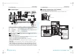
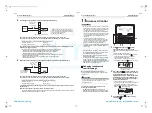
Connecting an electric damper (electric shutter) (External Output)
Connect to the terminal block for external output (3 and 4) in the electrical control box
Connection wire (locally procured): 2-core wire (H07 RN-F or 60245 IEC 66) 1.0mm
2
to 2.5mm
2
The electric damper (electric shutter) works during normal operation, 24-hour ventilation mode, and
nighttime heat purge operation.
• The electric damper (electric shutter) also works in the following circumstances:
* While the operation is stopped intermittently in 24-hour ventilation mode
* While the operation is paused during nighttime heat purge operation
* While operating in cold mode (Temperature is below
−
10°C.)
• The electric damper (electric shutter) does not work in the following circumstances:
* While the operation is stopped
* Before the monitoring operation of nighttime heat purge operation starts
* While in the delay mode
6
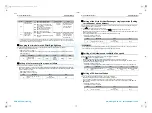
Monitoring an abnormal signal or the operation signal of bypass mode (External Output)
Connect to the terminal block for external output (3 and 5) in the electrical control box
Connection wire (locally procured): 2-core wire (H07 RN-F or 60245 IEC 66) 1.0mm
2
to 2.5mm
2
It is possible to monitor an abnormal signal or the operation signal of bypass mode from the Air to Air
Heat Exchanger.
Detection of an abnormal signal is possible, as factory default.
• To change settings so that the operation signal of bypass mode can be detected, refer to “Abnormal signal/
bypass mode signal output setting” on page 21.
Rated contact (3 to 5: Total value with abnormal signal output)
Maximum: 240VAC, 1A
Minimum: 220VAC, 100mA
24VDC, 1A
5VDC, 100mA
Rated contact (3 and 4: Total value with output of the electric damper)
Maximum: 240VAC, 1A
Minimum: 220VAC, 100mA
24VDC, 1A
5VDC, 100mA
Power supply
Contact
Electric
damper
Terminal block for external output
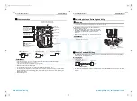
If external output is used working at a higher
voltage and current than the rated values, install
a relay according to the diagram above (diagram
for connecting an auxiliary fan).
Rated relay: 220-240VAC
220-240V~, 50Hz
220V~, 60Hz
Power supply
Contact
Terminal block for external output
Abnormal signal or
operation signal of
normal ventilation
220-240V~, 50Hz
220V~, 60Hz
11
Advanced Control
REQUIREMENT
• When the unit is used for the first time, it takes a while
for the remote controller to recognize operation input
after the power is turned on. This is not a malfunction.
• For details on the auto address setting of air
conditioners when operating together with a SMMS
series air conditioner (adjust the auto address setting
on the circuit board of the outdoor interface), refer to
the Installation Manual of the SMMS series air
conditioner.
• For details on the auto address setting of air
conditioners when operating together with a DI·SDI
series air conditioner (the action is performed when
the power is turned on), refer to the Installation
Manual of the DI·SDI series air conditioner.
• Turn on the Air to Air Heat Exchanger first. Refer to the
Installation Manual of the air conditioner about its
power supply.
• When shipped from the factory, all the settings are
set to [Factory default]. Change the settings of the
Air to Air Heat Exchanger if necessary.
• Change settings using the main remote controller
(wired remote controller).
* The settings cannot be changed using the wireless
remote controller, the sub remote controller, or a
system without a remote controller (system with only
the central remote controller). Therefore, prepare the
main remote controller and install it.
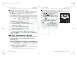
Changing the advanced
control settings
Basic procedure for changing the settings
Change settings while the power is turned off. (Stop
operation.)
CAUTION
Do not change any setting codes other than those in this
manual; otherwise, the unit may not work or some
problems may occur.
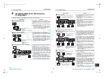
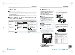
Changing the settings of the Air to Air Heat
Exchanger (For NRC-01HE)
* For RBC-AMT32E, AMS41E, settings can be
changed using the same procedure as NRC-01HE.
(Display position is different from that of NRC-01HE.)
1
Push
button and temp.
button
simultaneously for at least 4 seconds.
After a while, the display flashes as shown in the
figure.
Confirm that the CODE No. is [01].
• If the CODE No. is not [01], push
button to
erase the display content, and repeat the
procedure from the beginning.
(No operation of the remote controller is
accepted for a while after
button is pushed.)
2
Every time the
button is pressed, the
unit numbers of the indoor units or the Air to
Air Heat Exchangers in the group are
displayed successively. Select the Air to Air
Heat Exchanger to change settings. When
the unit is selected, the fan starts running to
indicate the selected unit.
* The unit number of the Air to Air Heat
Exchanger is 31-OO. OO represents the indoor
unit address specified with No.1 to No.4 of
SW702 and No.1 and No.2 of SW703. For NRC-
01HE, the
indicator lights up.
3
Using TEMP.
/
buttons, specify
CODE No. [
].
6
3
1
2
5
4
(* Display content varies with
the indoor unit model.)
33-EN
34-EN
+00ET9X463301_01EN.book Page 17 Thursday, January 20, 2011 4:41 PM
AMP Air Conditioning
www.ampair.co.uk | sales@ampair.co.uk

