6.
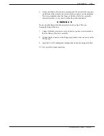
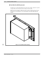
Gently, but firmly, slide the drive assembly into the slot until the connector
on the back of the assembly has mated with the connector on the backplane.
This is accomplished when the flange on the front of the drive assembly
sheetmetal reaches or very nearly reaches the cabinet sheetmetal.
◆
WARNING
◆
Do not slam the floppy disk drive assembly into the cabinet. This can
damage the floppy disk drive.
7.
Using a flat-blade screwdriver, screw in the two captive screws attached to
the front flange of the drive assembly.
8.
Connect keyed connector on the floppy signal cable to the connector on the
CPU board.
9.
Insert the L.6.X.X configuration backup diskette into the floppy disk drive.
10. Test system for proper operation.
Toshiba VP Systems Release 7.1
July, 1994
MAINTENANCE
5-95
Summary of Contents for VP 300
Page 2: ......
Page 10: ......
Page 14: ......
Page 20: ...Toshiba VP Systems Release 7 1 July 1994 ...
Page 52: ...Toshiba VP Systems Release 6 1 February 1993 2 14 Installation and Maintenance Manual ...
Page 56: ...Toshiba VP Systems Release 7 1 July 1994 ...
Page 146: ......
Page 312: ...Toshiba VP Systems Release 7 1 July 1994 ...
Page 314: ......
Page 444: ......
Page 496: ......
Page 542: ......
Page 598: ...Toshiba VP Systems Release 6 1 February 1993 ...
Page 600: ...Toshiba VP Systems Release 6 1 February 1993 ...

