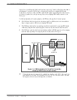
Figure 11-2 is a PBX configuration for Secondary Answering. In this configuration, the PBX is
programmed to forward a call for busy or unanswered stations to an outgoing PBX trunk
connected to a DAC port. Then, the PBX sends DTMF signals representing the called station’s
extension or mailbox over the tip and ring leads of the outgoing PBX trunk connected to the
DAC port.
For this configuration to function properly, the PBX must be capable of several options:
•
The PBX must allow external calls (incoming trunk) to a PBX station to be forwarded on
busy or ring-no-answer (RNA) to an outgoing PBX trunk.
•
The PBX must allow callers on incoming trunks to be transferred to outgoing PBX trunks
without requiring that the transferring party remain on the line (trunk-to-trunk transfer).
•
The PBX must send the called extension/station number in DTMF signal over the outgoing
trunk (in-band signaling). The outgoing trunk is connected to a DAC port.
☞
This application is also supported by standard line interface cards (LICs) when ports are
programmed in CX mode. This approach allows the VP 300 to transfer callers if desired
but requires callers to reenter the digits they just dialed.
Toshiba VP Systems
Release 6.1
February, 1993
11-4
Installation and Maintenance Manual
Figure 11-2 PBX Application for Trunk Port Connection
(Employs PBX Trunk-to-Trunk Transfer)
VP 300
DAC
I/O
Panel
PBX
CO
Demarcation
Trunk
Ports
DAC
Interface(s)
Stations
Any Type Trunks
–48 VDC
Summary of Contents for VP 300
Page 2: ......
Page 10: ......
Page 14: ......
Page 20: ...Toshiba VP Systems Release 7 1 July 1994 ...
Page 52: ...Toshiba VP Systems Release 6 1 February 1993 2 14 Installation and Maintenance Manual ...
Page 56: ...Toshiba VP Systems Release 7 1 July 1994 ...
Page 146: ......
Page 312: ...Toshiba VP Systems Release 7 1 July 1994 ...
Page 314: ......
Page 444: ......
Page 496: ......
Page 542: ......
Page 598: ...Toshiba VP Systems Release 6 1 February 1993 ...
Page 600: ...Toshiba VP Systems Release 6 1 February 1993 ...


