☞
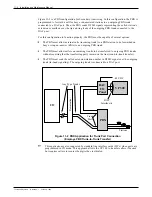
In the table, “1RING2” refers to the RING lead of channel 2 of the DAC card
plugged into the slot that connects to DP1 on the DAC I/O panel.
Toshiba VP Systems
Release 6.1
February, 1993
11-12
Installation and Maintenance Manual
Table 11-2 DAC I/O Panel DP EXT Connections
DP EXT PIN
NUMBER
SIGNAL
FUNCTION
DP EXT PIN
NUMBER
SIGNAL
FUNCTION
1
2
3
4
5
6
7
8
9
10
11
12
13
14
15
16
17
18
19
20
21
22
23
24
25
26
27
28
29
30
31
32
33
34
35
36
37
38
39
40
41
42
43
44
45
46
47
48
49
50
1RING1
1RING2
1RING3
1RING4
2RING1
2RING2
2RING3
2RING4
3RING1
3RING2
3RING3
3RING4
4RING1
4RING2
4RING3
4RING4
1TIP1
1TIP2
1TIP3
1TIP4
2TIP1
2TIP2
2TIP3
2TIP4
3TIP1
3TIP2
3TIP3
3TIP4
4TIP1
4TIP2
4TIP3
4TIP4
Summary of Contents for VP 300
Page 2: ......
Page 10: ......
Page 14: ......
Page 20: ...Toshiba VP Systems Release 7 1 July 1994 ...
Page 52: ...Toshiba VP Systems Release 6 1 February 1993 2 14 Installation and Maintenance Manual ...
Page 56: ...Toshiba VP Systems Release 7 1 July 1994 ...
Page 146: ......
Page 312: ...Toshiba VP Systems Release 7 1 July 1994 ...
Page 314: ......
Page 444: ......
Page 496: ......
Page 542: ......
Page 598: ...Toshiba VP Systems Release 6 1 February 1993 ...
Page 600: ...Toshiba VP Systems Release 6 1 February 1993 ...


