CONNECTING THE PHONE SYSTEM TO THE VP 300
This section explains the requirements for connecting the VP 300 to the PBX.
Connection
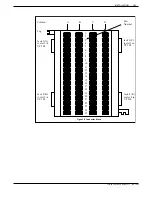
The VP 300 installation involves connecting 25-pair cables from the rear of the
Overview
VP 300 to a 66M4-4W connector block which is mounted on a backboard. Each
25-pair cable supports four ports, or one slot on the VP 300. The VP 300 is then
connected to the PBX using jumper wire.
It is recommended that the PBX extensions to be associated with the VP 300 be
terminated on a 66M connector block, or equivalent, for ease of installation and
fault isolation. Refer to the following diagram.
Verifying
The following equipment is necessary for installation of the VP 300:
Equipment
•
PBX extensions associated with the VP 300, to be terminated on a 66M
connector block, or equivalent
•
66M4-4W connector block — One for each four slots used on the VP 300
•
10-foot male-to-female 25-pair amphenol type cables — One for each slot
used on the VP 300
•
Self-tapping sheet metal screws
PBX
VP
300
25-pair cable
Bridge
clips
66M
66M4-4W
Cross-connect wire
PBX extensions
terminate
Figure 3-7 Typical VP 300 Connections
Toshiba VP Systems Release 7.1 July, 1994
INSTALLATION
3-31
3.10
Summary of Contents for VP 300
Page 2: ......
Page 10: ......
Page 14: ......
Page 20: ...Toshiba VP Systems Release 7 1 July 1994 ...
Page 52: ...Toshiba VP Systems Release 6 1 February 1993 2 14 Installation and Maintenance Manual ...
Page 56: ...Toshiba VP Systems Release 7 1 July 1994 ...
Page 146: ......
Page 312: ...Toshiba VP Systems Release 7 1 July 1994 ...
Page 314: ......
Page 444: ......
Page 496: ......
Page 542: ......
Page 598: ...Toshiba VP Systems Release 6 1 February 1993 ...
Page 600: ...Toshiba VP Systems Release 6 1 February 1993 ...


