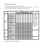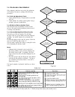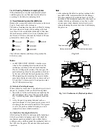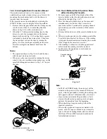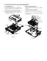
1-6-6. Worm Gear, Worm Gear Holder, Loading Motor
and Worm Wheel Replacement
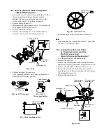
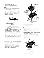
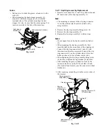
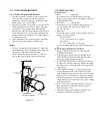
1. Release the claw (1) of the worm gear holder (2) from
the cutout portion of the mechanical deck by
bending it to the arrow direction, and remove the
worm gear holder (2) by pulling downward.
2. Remove the worm gear (3).
3. Before removing the worm wheel (3), first remove the
FL cam gear. (Refer to item 1-6-5.)
4. Remove the worm wheel (4).
5. Remove one securing screw (5) on the loading
motor (6), and remove the loading motor (6).
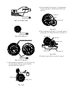
Fig. 1-6-18
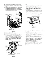
Fig. 1-6-13
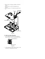
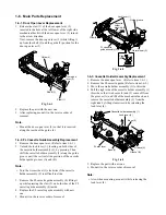
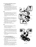
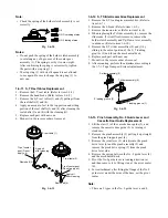
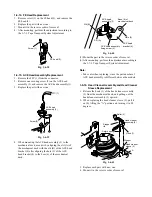
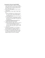
6. Replace each part with new one.
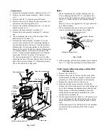
After replacing with new parts, apply an amount of
grease on the following portions.
Fig. 1-6-14 Worm gear
Fig. 1-6-16 Loading motor
Fig. 1-6-17 Worm wheel
7. Mount the parts in the reverse order of removal.
Note:
• After mounting the worm gear holder (2), check that
the claw (1) is locked properly.
1-6-7. Loading Drive Gear, Cam Slider,
S, T Loading Lever Assemblies,
Pinch Drive Lever and
Tension Drive Lever Replacement
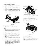
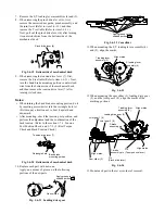
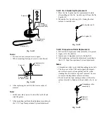
1. Turn the mechanical deck upside down.
2. Remove the reel belt.
3. Remove one securing screw on the joint gear bracket,
and remove the joint gear bracket. (Refer to item 1-6-5.)
4. Remove the joint gear 2. (Refer to item 1-6-5.)
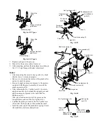
5. Release the claw (1) of the loading drive gear (2)
from the groove of the mechanical deck, and remove
the loading drive gear (2).
6. Remove the cam slider (3).
Loading motor (6)
Claw
(1)
Worm
gear (3)
Worm gear
holder (2)
Worm wheel (4)
Screw (5)
Apply grease to the
shaded portion .
Apply grease to the
shaded portion .
Fig. 1-6-15
Worm gear holder
Apply grease to the
shaded portion .
Apply grease to the
shaded portion .
Joint gear 1 (6)
Joint gear 2 (8)
Cam slider (3)
T loading lever
assembly (5)
S loading lever
assembly (4)
Loading drive gear (2)
Pinch drive lever pin
Tension drive
lever pin
Claw (1)

