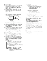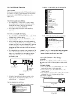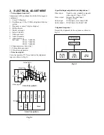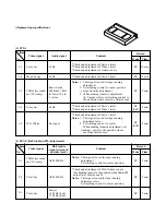
Notes:
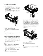
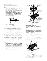
• Tightening order of the securing screws (1), (2) and
(3) is 294 to 392 mN•m (3 to 4kg•cm).
• Take care of the position inserting the FPC when
mounting the cylinder holding plate (4). (Refer to
item 1-6-19.)
• When replacing the cylinder holding plate (6), take
care not to damage the cylinder and the tape guides
etc.
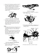
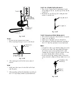
Note that the screw (3) of the cylinder holding plage
(5) does not touch with the head assembly (cylinder).
Fig. 1-6-46
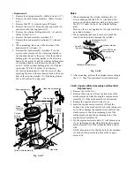
1-6-19. Head Assembly (Cylinder) Inspection and
Replacement
<Inspection>
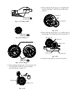
1. Check if the tape transport surface on the head
assembly (cylinder) is not damaged.
2. Check if the rotation of the head assembly (cylinder)
is not abnormal.
3. Check if the video head is not damaged and worn
out.
(It can be checked easier by using the head checker.)
4. Check if the video head is not clogged. (When it
can't be eliminated by cleaning)
5. Check if the FPC (A) is not damaged.
If some abnormality is found after checking above “1.”
to “5.”, replace the head assembly (cylinder) with new
one.
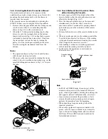
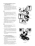
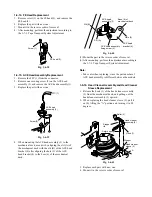
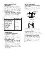
Be sure that driver does not
approach to cylinder.
Screwdriver
Cylinder holding plate (5)
Screw (3)
Head assembly
(Cylinder)
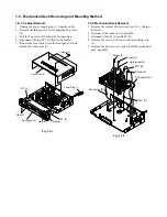
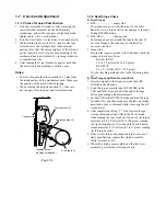
1-6-18. Cylinder Holding Plates Replacement
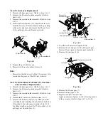
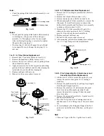
1. Remove the head cleaner assembly. (Refer to item 1-
6-16.)
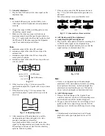
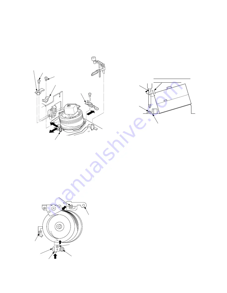
2. Remove three securing screws (1), (2) and (3) on the
cylinder holding plates (4), (5) and (6) Remove the
cylinder holding plates (4), (5) and (6) by sliding in
each direction shown by the arrows.
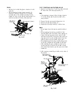
Head cleaner
assembly
Screw
(1)
Cylinder holding
plate (4)
Screw (2)
Cylinder holding plate (5)
Stopper at post side
Screw (3)
Cylinder holding plate (6)
Fig. 1-6-44
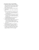
3. Replace each part with new one.
4. Mount it in the reverse order of removal.
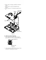
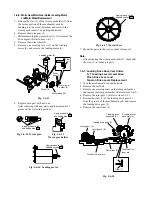
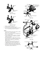
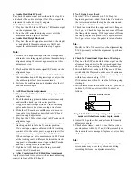
5. Fix the cylinder holding plate (4) and (5) with screws
(1) and (2) while pushing slightly in the directions
shown by the arrows. Fix the cylinder holding plate
(6) with screws (3) after matching the boss on the
mechanical deck to the boss hole on the cylinder
holding plate (6).
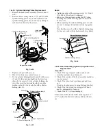
Cylinder holding plate (4)
Boss of
mechanical deck
Stopper at post side
Cylinder holding plate (5)
Protrusion
Screw (3)
Cylinder
holding
plate (6)
Screw (1)
Screw (2)
Fig. 1-6-45

