(3) Tape Transport System Adjustment
<Rough Adjustment>
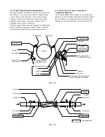
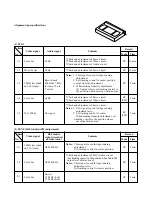
When the part(s) listed in Table 1-7-1 is replaced,
perform required adjustments by referring to procedures
for the tape transport system. When the part (s) listed in
Table 1-7-1 is replaced, the tape path may be changed
and may damage alignment tape. To prevent this, first
run a T-160 tape and make sure excessive tape wrinkle
does not occur at each tape guide.
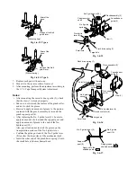
1. If tape wrinkle is observed at the S, T guide rollers,
turn the S, T guide rollers until wrinkle disappears.
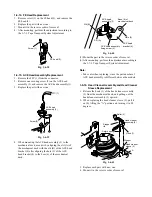
2. If tape wrinkle is observed at the No. 8 guide,
perform the tilt adjustment of the ACE head.
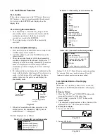
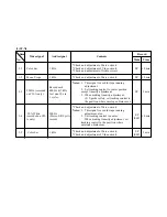
Table 1-7-1
<Adjustment Procedures>
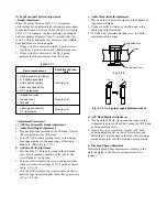
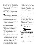
1) ACE Head Assembly Rough Adjustment
a. Audio Head Height Adjustment
1. Play back the tape recorded in the SP mode. Observe
the core portion of the ACE head.
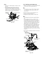
2. Turn the ACE height adjusting screw so that upper
tape edge matches to the upper edge of the audio
head core. (Refer to Fig. 1-7-5.)
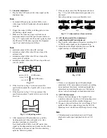
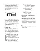
b. ACE Head Tilt Adjustment
1. Play back the T-160 tape recorded in the SP mode
and observe running condition of the tape at the
lower flange of No.8 guide.
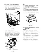
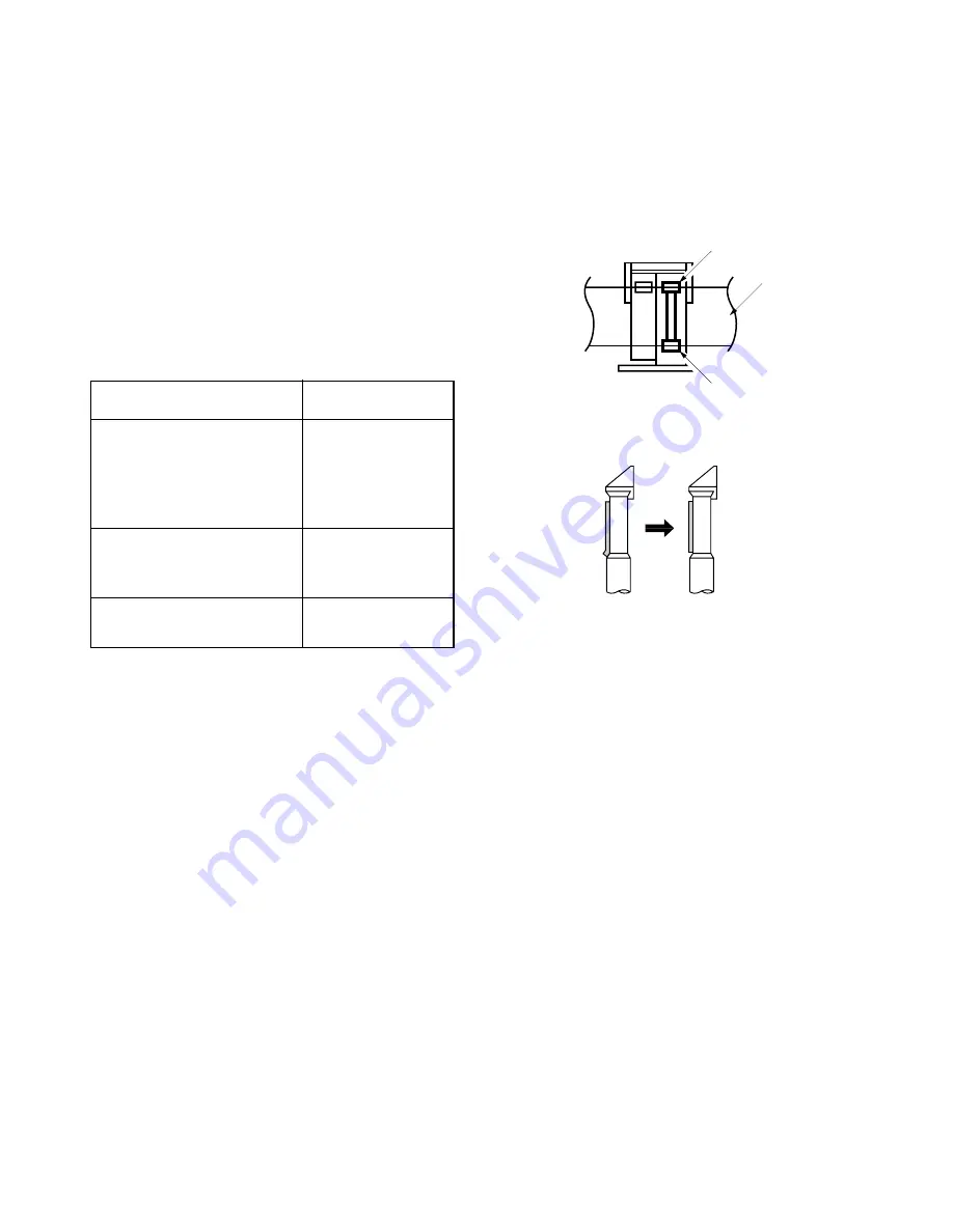
2. Turn the ACE tilt adjusting screw until tape wrinkle
is caused at the lower flange of No. 8 guide as shown
in Fig. 1-7-6 (A).
3. Turn the ACE tilt adjusting screw counter-clockwise
until the tape travels along the lower flange as shown
in Fig. 1-7-6 (B).
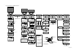
Adjustment proce-
dure
From item (a)
From item (c)
From item (d)
Parts replacement
• Head assembly (Cylinder)
• S, T sliders assembly
• ACE head assembly
• Pinch lever assembly
• No. 9 guide lever
• Impedance roller
• Tension lever
• FE head
• Clutch gear assembly
• S, T reel tables
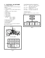
c. Audio Head Azimuth Adjustment
1. Play back the 7 kHz audio signal on the alignment
tape in the SP mode.
2. Connect a milli-voltmeter or oscilloscope to the
audio line output terminal.
3. Turn the ACE azimuth adjusting screw to obtain
maximum audio output.
Audio head core
Tape
Control head core
Fig. 1-7-5
[B]
[A]
Fig. 1-7-6 No. 8 guide rough adjustment check
d. ACE Head Position Adjustment
1. Play back the 2 MHz video envelope signal in the
alignment tape in the SP mode. Loosen the ACE head
position securing screw.
2. Insert a slot-type screwdriver into the ACE head
position adjusting slit on the ACE main base and
adjust the ACE main base so that the video envelope
reaches a peak level at the tracking center position.
2) Playback Phase Adjustment
Perform playback phase adjustment according to the
methods stated in the Electrical Adjustment (servo
system).

