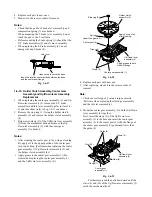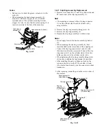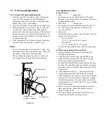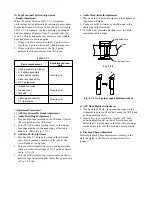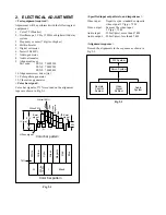
c. Audio Head Height Check
Play back the audio signal as described in the step 4) a.,
and check if the audio envelope is flat. If not, repeat the
adjustment described in step 4) a. again.
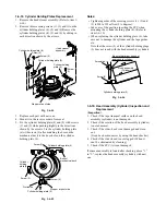
d. Audio Azimuth Adjustment
1. Play back the 400 Hz in SP mode, 7 kHz audio signal
on the alignment tape.
2. Turn the ACE azimuth adjusting screw until the
maximum audio output is obtained.
e. Audio Head Height Re-check
1. Play back the audio signal as described in the step 4)
a., and check if the audio envelope is flat. If not,
repeat the adjustment described in step 1) again.
Note:
• If there is no alignment tape with the stereophonic
alternative recording signal, perform the audio height
alignment using the current alignment tape at this
adjustment step.
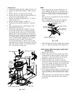
2. Playback the 400 Hz audio signal (SP mode) on the
alignment tape.
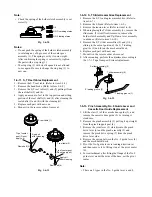
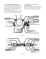
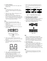
3. Turn each three alignment screw of the ACE head to
the same direction in 45 degrees steps evenly so that
the audio output level becomes maximum.
4. Perform the confirmation and adjustment for the tilt
and the azimuth again.
f. ACE Head Position Adjustment
1. Play back the SLP mode white envelope signal on the
alignment tape.
2. Push the tracking up/down buttons simultaneously
and reset the tracking at its center position.
3. Trigger the oscilloscope with the video switching
pulse and observe the video envelope waveform.
4. Slide the ACE main base until the maximum enve-
lope output is obtained as described in ACE head
position rough adjustment.
5. Play back the 2 MHz video signal in SP mode on the
alignment tape.
6. Make sure the envelope output is maximum when the
tracking control is placed at its center position.
If no envelope output is obtained with the tracking
control set to the center position, again adjust it for
maximum envelope output in SP and SLP modes.
When envelope output is maximum in the SLP mode
at the tracking center, difference between the track-
ing position of maximum envelope in the SP mode
and the tracking center is within 3ms.
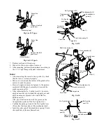
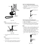
7. Tighten the ACE head position fixing screw and
secure the ACE main base.
g. After Completion of ACE Head Fine Adjustment
Apply screw lock to two screws (tilt, azimuth adjusting
screws) in front of the ACE head.
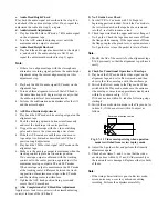
5) No. 9 Guide Lever Check
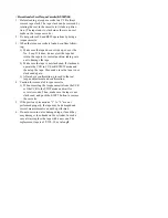
1. Set the VCR to Cue mode with T-160 tape (at
beginning portion) loaded. Switch the Cue mode to
the review mode when the tape has been rewound
into the T reel table to some extent.
2. Check tape wrinkle at the upper and lower flange of
No. 8 guide. Check the tape does not come off from
the flange while running. If the tape comes off from
the flange, replace the pinch lever, capstan motor or
No. 9 guide lever since the part(s) is (are) defective.
Note:
• Modify the lid of the cassette for the alignment tape
T-160 previously so that the alignment is performed
easily.
6) Check for Transitional Operation of Envelope
1. Play back the SLP mode white video signal on the
alignment tape, and set in Review mode, and then
observe the video envelope with the oscilloscope.
2. Switch the Review mode to the Play mode. When
switched to the Play mode, make sure the entrance
side envelope comes to an approximate steady state
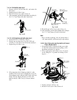
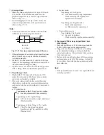
within 3s as shown in Fig. 1-7-11.
If it does not rise within 3s, take the following steps
starting 4.
3. Switch the cassette slot-in mode to the Play mode. As
in item 2., if it does not rise within 3s, adjust as
follows.
Envelope at entrance side
Fig. 1-7-11 Video envelope rising when operation
mode is switched from review to play mode
4. Adjust the S guide roller and perform the linearity
adjustment again.
5. Check above items 2. and 3. to see that the video
envelope rises within 3s. If not, S slider assembly or
the tension lever is damaged. Replace either (or both)
of them.
Note:
• If the rising characteristic is poor in Review mode,
screen noise may occur in synchronous editing
recording. Perform the adjustment carefully.

