< Specified input output levels, and impedance >
Video input:
Negative sync, standard composite
video signal 1 V(p-p), 75
Ω
Video output:
Same as the video input,
1 V(p-p), 75
Ω
Audio input:
308mV(rms), more than 47 k
Ω
Audio output:
308mV(rms), less than 4.7 k
Ω
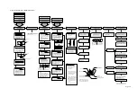
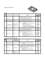
< Alignment sequence >
Proceed the alignments in the sequence as shown in
Fig. 2-2.
2. ELECTRICAL ADJUSTMENT
< Test equipment required >
Adjustment will be performed with the following test
equipment.
1. Color TV (Monitor)
2. Oscilloscope, 2 CHs, 15 MHz or higher with delay
system
3. Frequency counter (7 digits or higher)
4. Millivoltmeter
5. Digital voltmeter
6. Tester (20 k
Ω
/V)
7. Audio generator
8. Audio attenuator
9. Alignment tapes
Part code:
ST-N1: 70909202
ST-NF: 70909203
ST-N5: 70909401
10. Alignment screw driver (jig)
11. Color pattern generator
12. Video sweep generator
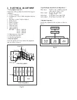
< Color bar signal >
Color bar signals of 75% recorded on the alignment
tapes are shown in Fig. 2-1.
1V (p-p)
0.7V
0.3V
Burst
signal
0.3V
Q
I
Color bar pattern
Q
I
Black
75%
Color bar pattern
White 100%
White
Yellow
Cyan
Green
Magenta
Red
Blue
H Sync signa
l
White(75%)
Yellow
Cyan
Blue
Red
Magenta
Green
White(100%)
Burst
signal
Fig. 2-1
Servo System
PIF System
Remote
Control
System
Video
Signal
System
Audio
System
Fig. 2-2

