1.AC Plug-in
2.Power SW ON
3.Cassette-in and
Cassette-out
4.Key entry operation
(Remote control)
5.Special Functions
Auto Power ON
Auto Play.
Auto Rewind
INDEX
Tape Remain Indicator
Tracking
Auto Speed Select
6.Playback Function
Picture Sharpness
Tone Quality
Others
7.REC/PLAY Function
Picture Sharpness
Tone Quality
Others
Clock setting
Timer/counter, SP/SLP, TV/
VCR, SW, Channel selection,
EE picture and tone quality,
TV/VCR switch (in TV)
Cassette-in-Cassette loading
Eject
Cassette-out
REC, PLAY
Cue/Review
Still, Frame feeding/slow
FF/REW
Cassette-in at Power OFF
Loading of tape with safety tab
REC/PLAY/CUE
Registering Index Signal
“ REMAIN/COUNTER ”
Digital tracking
Timer setting
PLAY
(Test tape : ST-N1/ST-NF)
Cue/Review
Still/Slow
REC/PLAY
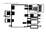
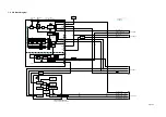
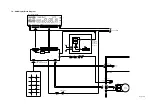
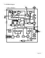
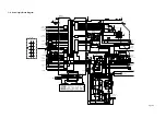
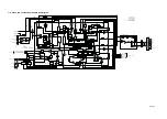
Circuit
Diagram
8-2-1
8-2-1
8-2-1
8-2-1
8-2-1
8-2-1
8-2-1
8-2-1
8-2-1
8-2-1
8-2-1
8-2-1
8-2-1
8-2-1
8-2-1
8-2-1
8-2-1
8-2-1
8-2-1
8-2-1
8-2-1
Fig No.
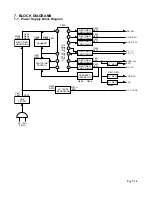
Block
Diagram
7-1-1
7-3-1
7-1-1
7-5-1
7-2-1
7-6-1
7-7-1
7-5-1
7-5-1
7-1-1
7-5-1
7-5-1
7-5-1
7-5-1
7-5-1
7-6-1
7-7-1
7-5-1
7-6-1
7-7-1
7-5-1
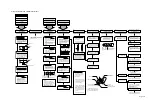
Inspection block
Power (AC system)
KDB
Power
Logic
PIF
Video (EE, Rec mode)
Audio (EE, Rec mode)
Logic
Logic
Power
Logic
Servo system
Logic
Servo
Logic
Video PLAY system
Audio PLAY system
Servo system
Video PLAY system
Audio PLAY system
Servo system
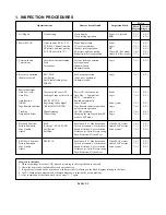
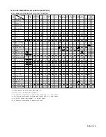
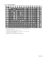
Table 1-1
1. INSPECTION PROCEDURES
Items to be confirmed
Clock display
Clock setting operation
Mode display lamp
TV receive condition
Channel select operation,
EE picture and tone quality,
Signal level, Stereo operation
Cassette loading operation
Eject operation
Indicator lamp
Abnormal sound
Each mode operation
(Tape drive operation)
Abnormal sound
Power ON, Cassette down
Auto Play — Completion —
REW — Completion —
Rewind automatically
Index Search
Tape Remain indicator operation,
quick remain operation
ON/OFF switching
Changing the tape speed from SP
mode to SLP mode
Resolution, S/N, Hue, Saturation,
Color unevenness, Color dropout,
Sound distortion, Level variation,
Picture noise, Jitter, Picture swing,
Skew distortion, Flicker, Beat
Resolution, S/N, Hue, Saturation,
Color unevenness, Color dropout,
Sound distortion, Level variation,
Picture noise, Jitter, Picture swing
Skew distortion, Flicker, Beat
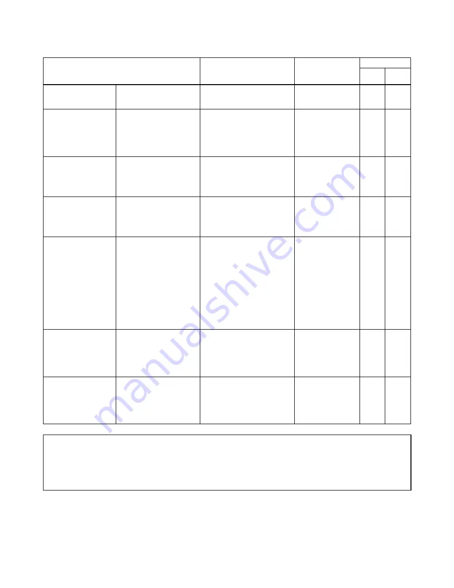
How to use the table
1. When inspecting a defective VCR, proceed according to the steps showin in the table.
2. Check the items to be confirmed for each operation step.
3. If a problem is found on the item, check waveforms (level) referring to the block diagram relating to the items.
4. Use PC board pattern diagram and schematic diagram to examine the circuit precisely.
5. After completion of the repair work, check steps 1 –
7 again.
Operation steps

