1-8. Self-Check Function
1-8-1. Outline
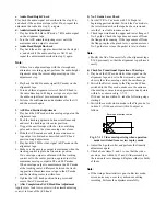
When a tape running stops or the VCR enters the power
OFF mode, etc. due to some abnormality, the abnormal-
ity is stored in the EEPROM and displayed on the
display tube.
1-8-2. Storing Abnormal Modes
1. The abnormality is classed into 5 groups, and the
abnormality number, system control mode, and the
mechanism position at which the abnormality
occurred are stored in the EEPROM.
2. The writing timing is just after the abnormality
occurred.
1-8-3. Abnormality Mode Display
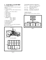
1. Press the CH UP and CH DOWN buttons on the VCR
simultaneously for more than 5s.
2. And then within 2s, press the PAUSE button on the
remote control.
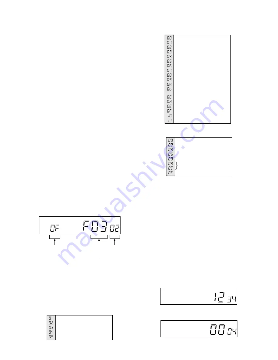
3. The system control mode at which the abnormality
occurred is displayed at the channel display area, “F”
is displayed at the hour digit, abnormality generation
number is displayed at the minute digit, and the
mechanism position is displayed in the second digit
position.
4. The abnormality mode display is not indicated in the
mode with the display tube turned off, such as saving
mode, etc. In this case, after confirming the abnor-
mality status, turn the power on and display the
abnormality mode.
Standby
Stop
Rewind
Review
FF
Cue
Playback
Still, slow playback
X2 speed
Unloading stop
Reverse playback
Still in reverse playback,
Reverse slow playback
Recording
Record pause
Power off eject
Eject
Short FF
Short REW
Cylinder stop
Reel abnormality (take up)
Reel abnormality (supply)
Abnormal slot in/slot out
Abnormal loading
F/L driving
Loading/unloading
Reverse rotation with pinch roller ON
Playback with pinch roller ON
Stop with main brake ON
Position detection impossible
FF/REW
Abnormal system
control modes
Abnormal
mechanism
positions
abnormality generation
number
Fig. 1-8-1
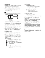
5. When the Counter Reset button is pressed in the
display period, the abnormality display data is
initialized and “–” is displayed.
The data displayed are as follows:
Table 1-8-1 Abnormality generation number
Table 1-8-2 Abnormal system control modes
Table 1-8-3 Abnormal mechanism positions
Positions 01, 03, 05, 07, 09 and 0B exist as mechanism positions.
For example, 05 shows a position between 04 and 06
(between playback position and review position).
1-8-4. Cylinder Rotation Time Display
(1) Outline
All the time for which the cylinder is ON is counted,
memorized on EEPROM, and indicated on the display
tube.
(2) Display Method
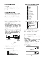
1. Press the “CH UP” and “CH DOWN” button on the
main unit for more 5 s at the same time.
2. Next, within 2 s press the “STOP” button on the
remote control.
3. The cumulative operation time of the cylinder will be
displayed for 30 s. The time unit is an hour.
(3) Example of Display
1. In case of 1234 hours.
Fig. 1-8-2
2. In case of 4 hours.
Fig. 1-8-3

