Slit (B)
ACE head assembly
fixing screw (2)
ACE head
bracket (4)
ACE head
assembly (3)
Boss (6) of
mechanical deck
Hole (5)
Slit (A)
Roller (4)
Stopper
rib
Head cleaner
assembly (2)
Hook (1)
Stopper
Return spring
Head cleaner
sleeve (3)
A
Screw (1)
FE head (2)
FFC (1)
ACE head
assembly (3)
Screw (2)
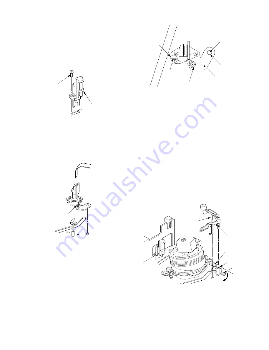
1-6-14. FE Head Replacement
1. Remove screw (1) on the FE head (2), and remove the
FE head (2).
2. Replace the part with new one.
3. Mount it in the reverse order of removal.
4. After mounting, perform the adjustment according to
the 1-7-3. Tape Transport System Adjustment.
Fig. 1-6-38
1-6-15. ACE Head Assembly Replacement
1. Remove the FFC (1) from the connector.
2. Remove one securing screw (2) on the ACE head
assembly (3), and remove the ACE head assembly (3).
3. Replace the part with new one.
Fig. 1-6-39
4. When mounting the ACE head assembly (3) to the
mechanical deck, mount it by aligning the slit (A) of
the mechanical deck with the slit (B) of the ACE head
bracket (4) after aligning the hole (5) of the ACE
head bracket (4) to the boss (6) of the mechanical
deck.
Fig. 1-6-40
(5) Mount the part in the reverse order of removal.
(6) After mounting, perform the adjustment according to
the 1-7-3. Tape Transport System Adjustment.
Note:
• Take care when replacing, since the part number of
ACE head assembly is different between the models.
1-6-16. Head Cleaner Assembly and Head Cleaner
Sleeve Replacement
1. Release the hook (1) of the head cleaner assembly
(2) from the mechanical deck, and pulling out the
head cleaner assembly (3) upward.
2. When replacing the head cleaner sleeve (3), pull it
out by lifting the “A” portion and turning it in 90
degrees.
Fig. 1-6-41
3. Replace each part with new one.
4. Mount it in the reverse order of removal.


