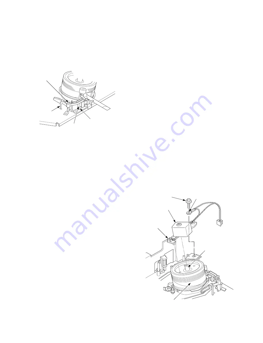
Head assembly (Cylinder)
FPC
Stopper (6)
Stopper rib (5)
Return spring (7)
Head cleaner
assembly (2)
1-6-17. Slip Ring Assembly Replacement
1. Remove two connectors (1) and (2) (cylinder side and
PC board side) of the slip ring assembly (3).
Note:
• The mounting or removal of the slip ring connector
(1) on the cylinder side should be carried out by
using tweezers.
2. Remove the slip ring assembly fixing screw (4).
3. Remove the slip ring assembly (3).
4. Replace the slip ring assembly (3) with new one.
Notes:
• Do not apply force to the head assembly (cylinder)
(5).
• When mounting the slip ring assembly (3), first,
insert the shaft to the center hole of the coupling (6).
• Connect the slip ring connectors (1) and (2) with
their insertion direction corrected. (Connect the slip
ring connector (1) on the cylinder side with its wire
holder portion set to the cylinder center side.)
• When tightening the slip ring assembly fixing screw
(4), be sure to tighten the lug terminal (6) together.
• After mounting the parts, confirm no slack on the
connector lead wire on the PC board side is found.
(If a slack is found, surely wire the connector without
slackened.)
5. After replacing, mount the part in the reverse order of
the removal.
Slip ring assembly
fixing screw (4)
Slip ring connector (2)
(PC board side)
Slip ring assembly (3)
Slip ring
connector (1)
(Cylinder side)
Coupling (6)
Lug terminal (6)
Head assembly (5)
(Cylinder)
Fig. 1-6-43
Notes:
• Take care not to stick the grease, oil and etc. on the
roller (4).
• When mounting the head cleaner assembly (2),
mount it so that the stopper rib (5) sits inside
(cylinder side) of the cylinder mounting bracket
stopper (6). Also, be sure that the return spring (7) is
inserted correctly in the hole of the main base.
Fig. 1-6-42


