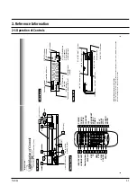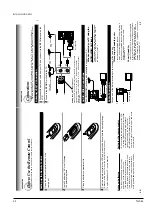
Reference Information
2-6
Toshiba
19
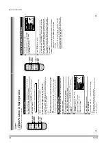
PLAYBACK
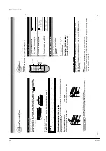
Adjusting the tracking
When playback starts, the VCR automatically adjusts the tracking for clear pictures and sound
(Digital Auto
T
racking).
If the VCR cannot locate the best possible tracking point,
hold down one of
CH/TRK
to adjust the
tracking manually
.
Notes
•
During the adjusting, the playback picture and sound may be distorted.
•
The digital auto tracking is activated only in the playback mode.
•
The noise on the screen may not be completely eliminated depending on the tape used, especially when the
tape was recorded on another VCR.
Basic Playback
1
Load a recorded cassette.
Power is turned on.
If the cassette has no safety tab,
playback starts automatically
.
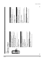
2
Press
PLA
Y
to start playback.
3
T
o
stop playback, press
ST
OP
.
To resume normal playback
Press
PLA
Y
again
Rewinding / Fast-forwarding
Press
REW
or
FF
in the stop mode.
S
SLP
VCR
REC
L
TIMER
S
S
L
P
VCR
REC
L
TIMER
PLA
YBACK
Playbac
k
This section explains the basic playback operation.
Preparation
•
Select the video channel (3 or 4) or video input mode on the TV.
•
Press VCR to set the remote control operating the VCR.
S
S
L
P
VCR
REC
L
TIMER
REW
CH/TRK
FF
3
2
1
Press
PLA
Y
during playback.
A tape runs at double speed
playback.
Double Speed Playback
18
V
ideo Cassette Use
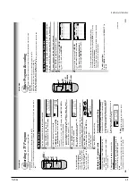
Loading a cassette
Push the cassette into the cassette compartment with the window side facing up and the
label side towards the front.
The VCR is automatically turned on.
The indicator will
appear in the VCR display
.
Ejecting a cassette
Press
EJECT
.
The cassette is ejected from the cassette compartment.
W
arning
Do not insert your hands or any foreign objects into the compartment.
This may result
in injury or damage.
T
ake special care with children to avoid accidents.
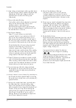
Precautions when using video cassettes
V
ideo cassettes have a safety tab to prevent accidental erasure. If the tab has already been removed,
recording cannot be performed.
T
o
prevent accidental erasure
Remove this safety tab with a screwdriver
.
T
o
record again
Cover the tab hole with adhesive tape.
•
A
void exposing cassettes to direct sunlight. Keep them away from heaters.
A
void extreme humidity
, vibrations or shock, strong magnetic fields (near a motor
, transformer or
magnet) and dusty place.
PREP
ARA
TION
V
ideo Cassette Use
Summary of Contents for W603C
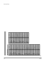
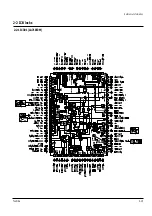
Page 20: ...Reference Information Toshiba 2 13 2 2 1 IC301 LA71072M 2 2 IC Blocks ...
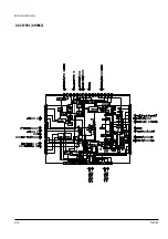
Page 21: ...Reference Information 2 14 Toshiba 2 2 2 IC501 AN3662 ...
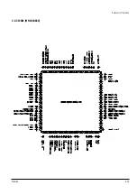
Page 22: ...Reference Information Toshiba 2 15 2 2 3 IC601 MN101D02X ...
Page 23: ...Reference Information 2 16 Toshiba MEMO ...
Page 25: ...Product Specifications 3 2 Toshiba MEMO ...
Page 56: ...Alignment and Adjustment Toshiba 5 11 Fig 5 21 Main PCB Top View VR501 Location for VR501 ...
Page 57: ...5 12 Toshiba Alignment and Adjustment MEMO ...
Page 59: ...Exploded View 6 2 Toshiba 6 1 Packing Assembly A702 A701 A702 Y101 Y102 UT01 ...
Page 63: ...Exploded View 6 6 Toshiba MEMO ...
Page 73: ...Replacement Parts List 7 10 Toshiba MEMO ...
Page 74: ...Toshiba 8 1 8 Block Diagram ...
Page 75: ...Block Diagram 8 2 Toshiba MEMO ...
Page 76: ...Toshiba 9 1 9 PCB Diagrams 9 2 9 3 9 3 9 3 9 1 Main 9 2 VFD 9 3 Jack 9 4 Key ...
Page 77: ...PCB Diagrams 9 2 Toshiba 9 1 Main ...
Page 78: ...PCB Diagrams Toshiba 9 3 9 2 VFD 9 3 Jack 9 4 Key ...
Page 79: ...PCB Diagrams 9 4 Toshiba MEMO ...
Page 82: ...Schematic Diagrams Toshiba 10 3 10 1 S M P S Power ...
Page 83: ...Schematic Diagrams 10 4 Toshiba IC601 VFD 10 2 Logic ...
Page 85: ...Schematic Diagrams 10 6 Toshiba 10 3 A V ...
Page 87: ...Schematic Diagrams 10 8 Toshiba 10 4 Hi Fi MTS ...
Page 89: ...Schematic Diagrams 10 10 Toshiba 10 5 TM Block Input Ouput ...
Page 90: ...Schematic Diagrams Toshiba 10 11 10 6 VFD ...
Page 91: ...Schematic Diagrams 10 12 Toshiba 10 7 Remote Control ...


