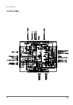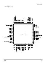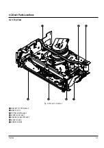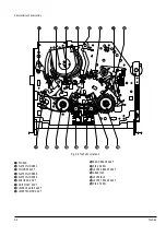
Reference Information
Toshiba
2-11
29
ADDITIONAL INFORMATION
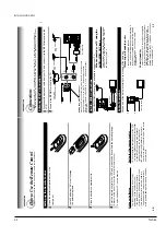
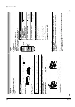
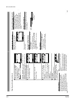
Setting Contr
ol Codes
1
Press
TV
to set the remote control operating your
TV
.
2
3
Release
TV
.
4
Point the remote control at your
TV and use each button
listed below to make sure that your
TV is operated correctly
.
POWER
T
o
turn the
TV on or of
f.
CH/TRK
T
o
select
TV channels in the upper or lower
direction.
VOL
T
o
adjust
TV sound level.
INPUT SELECT
T
o
select an external source such as a VCR.
Number buttons
T
o
select
TV channels. When selecting channels
1 to 9, first enter 0 and then the desired number
.
100
T
o
substitute for 100 channel key
.
DISPLA
Y
T
o
turn on or of
f
TV
’s screen display
.
ENTER
T
o
use for the
TV
’s ENTER key
.
Important
Some
TVs may not respond to all the operations above, or
may not be operated at all with this remote control. In this
case, operate your
TV with its own remote control.
Notes
•
For some brands, several control codes (brand codes) are allocated. Try
each of them until the buttons work on your TV.
•
If you replace the remote control
’s batteries, set the brand code again.
Multi Brand Remote Control
The remote control can be compatible with various brands of TV by setting their control codes. The
TOSHIBA code has initially been set to control TOSHIBA TVs.
ADDITIONAL
INFORMA
TION
While holding down
TV
. enter the two digits of your
TV
’s
brand code (listed on page 30) using
number buttons
.
DISPLA
Y
ENTER
PO
WER
CH/TRK
VO
L
100
INPUT SELECT
Number b
uttons
1,2,3
28
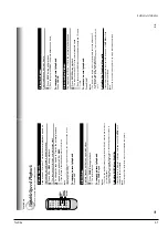
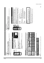
MTS Broadcast Compatibility
This VCR can receive or record MTS (Multichannel TV Sound) broadcasts. By connecting the VCR to
your stereo system or stereo TV, you will experience the SAP or stereo sound.
Preparation
Connect a stereo TV or stereo system to the AUDIO OUT jacks of the VCR.
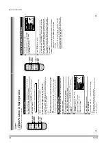
Recor
ding the SAP/Stereo Br
oadcast
1
On the SET UP screen (page 14),
select
“SAP SET
” using
CURSOR
(
▲
) or
(
▼
), and set to
“ON
” using
CURSOR ( )
or
( )
.
2
Press
PROG
. twice to exit.
3
Perform a recording.
SAP
(Second
Audio Program broadcast):
A separate audio program, usually broadcast in a second language with the
main language.
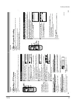
Selecting a sound
Sounds recorded on the tape
According to your setting of
“SAP
SET
” on the SET
UP
screen, the sound is recorded onto dif
ferent
tracks of the tape as below
. Set
“SAP
SET
” to
“ON
” or
“OFF
” appropriately
.
Hi-Fi sound track
Contents of recorded sound
On-Screen Display
(Press
DISPLAY
.)
Setting of
“SAP SET
”
on the
SET UP
screen
Type of receiving
broadcast
Normal sound
track (Mono)
L
R
“SAP
”“
STEREO
”
“ON
” or
“OFF
”
not lit
not lit
MONO
MONO
MONO
“ON
” or
“OFF
”
not lit
lit
MONO (MIXED)
“ON
”
lit
not lit
MONO
MONO
SAP
“OFF
”
lit
not lit
MONO
MONO
MONO
“ON
”
lit
lit
MONO
MONO
SAP
“OFF
”
lit
lit
MONO (MIXED)
STEREO
STEREO
Regular
(monaural audio)
Stereo
SAP
SAP
Sounds in playback
Y
ou can play SAP
and/or stereo broadcasts with this VCR. Press
AUDIO SELECT
to select a desired
sound.
Note
When the TV is connected to the RF OUT terminal of the VCR, the output sound is monaural.
Desired sound
SAP sound
Stereo sound
L , R indicators in the VCR display
R (right) is on.
Both R (right) and L (left) are on.
Sound output
SAP
Stereo
RECORDING
E
n
D : PROG
SET UP
PRESET
PROGRAM
TAPE LE
n
GTH
120 160 180
SAP SET
on off
COU
n
TER MEM
on off
LA
n
GUAGE E
n
G FRA ESP
▼
▼
A
UDIO
SELECT
2
1
DISPLA
Y
Summary of Contents for W603C
Page 20: ...Reference Information Toshiba 2 13 2 2 1 IC301 LA71072M 2 2 IC Blocks ...
Page 21: ...Reference Information 2 14 Toshiba 2 2 2 IC501 AN3662 ...
Page 22: ...Reference Information Toshiba 2 15 2 2 3 IC601 MN101D02X ...
Page 23: ...Reference Information 2 16 Toshiba MEMO ...
Page 25: ...Product Specifications 3 2 Toshiba MEMO ...
Page 56: ...Alignment and Adjustment Toshiba 5 11 Fig 5 21 Main PCB Top View VR501 Location for VR501 ...
Page 57: ...5 12 Toshiba Alignment and Adjustment MEMO ...
Page 59: ...Exploded View 6 2 Toshiba 6 1 Packing Assembly A702 A701 A702 Y101 Y102 UT01 ...
Page 63: ...Exploded View 6 6 Toshiba MEMO ...
Page 73: ...Replacement Parts List 7 10 Toshiba MEMO ...
Page 74: ...Toshiba 8 1 8 Block Diagram ...
Page 75: ...Block Diagram 8 2 Toshiba MEMO ...
Page 76: ...Toshiba 9 1 9 PCB Diagrams 9 2 9 3 9 3 9 3 9 1 Main 9 2 VFD 9 3 Jack 9 4 Key ...
Page 77: ...PCB Diagrams 9 2 Toshiba 9 1 Main ...
Page 78: ...PCB Diagrams Toshiba 9 3 9 2 VFD 9 3 Jack 9 4 Key ...
Page 79: ...PCB Diagrams 9 4 Toshiba MEMO ...
Page 82: ...Schematic Diagrams Toshiba 10 3 10 1 S M P S Power ...
Page 83: ...Schematic Diagrams 10 4 Toshiba IC601 VFD 10 2 Logic ...
Page 85: ...Schematic Diagrams 10 6 Toshiba 10 3 A V ...
Page 87: ...Schematic Diagrams 10 8 Toshiba 10 4 Hi Fi MTS ...
Page 89: ...Schematic Diagrams 10 10 Toshiba 10 5 TM Block Input Ouput ...
Page 90: ...Schematic Diagrams Toshiba 10 11 10 6 VFD ...
Page 91: ...Schematic Diagrams 10 12 Toshiba 10 7 Remote Control ...


