Toshiba
2-1
9
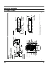
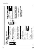
Rear Panel
LINE IN 1
AUDIO (Rear), 2 (Front) jacks
If the connected equipment is monaural (has one audio output jack), connect the L (MONO) side, the same
sound is recorded on both L and R on the Hi-Fi track.
Multifunctional
indicator
REC (Recording)
indicator
VCR indicator
Tape speed indicator (SP/SLP)
Cassette indicator
Timer recording indicator
STEREO indicator
Hi-Fi indicator
SAP indicator
Hi-Fi (L/R) indicators
L: Left channel
R:Right channel
off: Normal track
VCR Display
Hi-Fi
STEREO
SLP
SAP
VCR
REC
L
R
TIMER
INTRODUCTION
L
R
CH selector (3/4)
LINE OUT AUDIO jacks (L, R)
LINE OUT VIDEO jack
RF IN (FROM ANT.) terminal
LINE IN 1 AUDIO jacks (L, R)
RF OUT (TO TV) terminal
LINE IN 1 VIDEO jack
CH
OUT
(TO TV)
IN
(FROM ANT.)
LINE
OUT
LINE
IN 1
VIDEO
AUDIO
34
RF
To wall outlet
8
CHAN
N
E
L
PL
A
Y
STO
P
FF
EJECT
PO
W
E
R
REW
24
19
19
19
19
14
18
10
9
18
VIDEO
L/MONO A
UDIO R
LINE IN 2
REC
24
Fr
ont Panel
Remote Contr
ol
INTRODUCTION
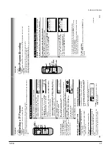
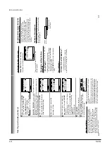
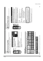
Identification of Controls
See the page in
for details.
This manual shows the names of buttons in italics.
CHANNEL
Remote
Sensor
VCR Display
STOP
PLAY
FF
Cassete compartment
REW
EJECT
POWER
LINE IN 2 VIDEO jack
LINE IN 2 AUDIO
(L/MONO, R) jacks
REC
PO
WER
14
24
TV/VCR
CH/TRK
19
COUNTER
22
100
17
22
SP/SLP
24
TIMER
26
FF
19
PLA
Y
19
P
A
USE
20
CURSOR
ENTER
14
INPUT SELECT
24
A
UDIO SELECT
24
Number b
uttons
DISPLA
Y
22
PR
OG
14
CANCEL
27
SLO
W
21
VCR
14
REC
24
TV
REW
19
ST
OP
19
29
28
14
V
OL/C.RESET
2. Reference Information
2-1 Operation of Controls
Summary of Contents for W603C
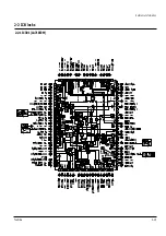
Page 20: ...Reference Information Toshiba 2 13 2 2 1 IC301 LA71072M 2 2 IC Blocks ...
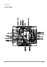
Page 21: ...Reference Information 2 14 Toshiba 2 2 2 IC501 AN3662 ...
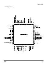
Page 22: ...Reference Information Toshiba 2 15 2 2 3 IC601 MN101D02X ...
Page 23: ...Reference Information 2 16 Toshiba MEMO ...
Page 25: ...Product Specifications 3 2 Toshiba MEMO ...
Page 56: ...Alignment and Adjustment Toshiba 5 11 Fig 5 21 Main PCB Top View VR501 Location for VR501 ...
Page 57: ...5 12 Toshiba Alignment and Adjustment MEMO ...
Page 59: ...Exploded View 6 2 Toshiba 6 1 Packing Assembly A702 A701 A702 Y101 Y102 UT01 ...
Page 63: ...Exploded View 6 6 Toshiba MEMO ...
Page 73: ...Replacement Parts List 7 10 Toshiba MEMO ...
Page 74: ...Toshiba 8 1 8 Block Diagram ...
Page 75: ...Block Diagram 8 2 Toshiba MEMO ...
Page 76: ...Toshiba 9 1 9 PCB Diagrams 9 2 9 3 9 3 9 3 9 1 Main 9 2 VFD 9 3 Jack 9 4 Key ...
Page 77: ...PCB Diagrams 9 2 Toshiba 9 1 Main ...
Page 78: ...PCB Diagrams Toshiba 9 3 9 2 VFD 9 3 Jack 9 4 Key ...
Page 79: ...PCB Diagrams 9 4 Toshiba MEMO ...
Page 82: ...Schematic Diagrams Toshiba 10 3 10 1 S M P S Power ...
Page 83: ...Schematic Diagrams 10 4 Toshiba IC601 VFD 10 2 Logic ...
Page 85: ...Schematic Diagrams 10 6 Toshiba 10 3 A V ...
Page 87: ...Schematic Diagrams 10 8 Toshiba 10 4 Hi Fi MTS ...
Page 89: ...Schematic Diagrams 10 10 Toshiba 10 5 TM Block Input Ouput ...
Page 90: ...Schematic Diagrams Toshiba 10 11 10 6 VFD ...
Page 91: ...Schematic Diagrams 10 12 Toshiba 10 7 Remote Control ...


