OPERATION
DESCRIPTION
Toshiba
3-1
3. Product Specifications
Specifications and features are subject to change without notice.
Power supply
Power consumption
External dimensions
Mass
Channels received
Antenna input/output terminals
Signal system
Recording/Playback system
Cassette
Tape speed
Video recording/Playback time
Fast forward/Rewind time
Video input
Video output
Audio input
Audio output
Audio frequency range(Hi-Fi)
Audio dynamic range(Hi-Fi)
Utilization conditions
120V AC, 60Hz
18W
430 x 94 x 252 mm (W.H.D)
3.0 kg
VHF : Channels 2-13
UHF : Channels 14-69
CATV : Channels A7-A1, A-CC, 66-125
UHF/VHF : 75ohm F type connector
Standard NTSC
Recording : VHS format (SP, SLP)
Playback : VHS format (SP, LP, SLP)
Video cassette with VHS mark
SLP : 11.1 mm/s,
SP : 33.4 mm/s
SLP : 480 minutes,
SP : 160 minutes (When T-160 video cassette is used.)
Within approx. 120 s (When T-120 video cassette is used.)
1V(p-p), 75 ohm, unbalanced, negative sync., pin jack
1V(p-p), 75 ohm, unbalanced, negative sync., pin jack
Line input : 308 mV(rms), more than 47 Kohm, pin jack
Line input : 308 mV(rms), more than 47 Kohm, pin jack
20Hz - 20KHz
68dB
Temperature : 5°C to 40°C
Humidity : less than RH 80%
Summary of Contents for W603C
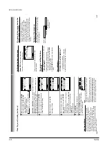
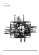
Page 20: ...Reference Information Toshiba 2 13 2 2 1 IC301 LA71072M 2 2 IC Blocks ...
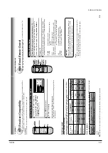
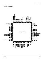
Page 21: ...Reference Information 2 14 Toshiba 2 2 2 IC501 AN3662 ...
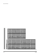
Page 22: ...Reference Information Toshiba 2 15 2 2 3 IC601 MN101D02X ...
Page 23: ...Reference Information 2 16 Toshiba MEMO ...
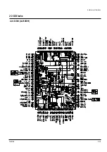
Page 25: ...Product Specifications 3 2 Toshiba MEMO ...
Page 56: ...Alignment and Adjustment Toshiba 5 11 Fig 5 21 Main PCB Top View VR501 Location for VR501 ...
Page 57: ...5 12 Toshiba Alignment and Adjustment MEMO ...
Page 59: ...Exploded View 6 2 Toshiba 6 1 Packing Assembly A702 A701 A702 Y101 Y102 UT01 ...
Page 63: ...Exploded View 6 6 Toshiba MEMO ...
Page 73: ...Replacement Parts List 7 10 Toshiba MEMO ...
Page 74: ...Toshiba 8 1 8 Block Diagram ...
Page 75: ...Block Diagram 8 2 Toshiba MEMO ...
Page 76: ...Toshiba 9 1 9 PCB Diagrams 9 2 9 3 9 3 9 3 9 1 Main 9 2 VFD 9 3 Jack 9 4 Key ...
Page 77: ...PCB Diagrams 9 2 Toshiba 9 1 Main ...
Page 78: ...PCB Diagrams Toshiba 9 3 9 2 VFD 9 3 Jack 9 4 Key ...
Page 79: ...PCB Diagrams 9 4 Toshiba MEMO ...
Page 82: ...Schematic Diagrams Toshiba 10 3 10 1 S M P S Power ...
Page 83: ...Schematic Diagrams 10 4 Toshiba IC601 VFD 10 2 Logic ...
Page 85: ...Schematic Diagrams 10 6 Toshiba 10 3 A V ...
Page 87: ...Schematic Diagrams 10 8 Toshiba 10 4 Hi Fi MTS ...
Page 89: ...Schematic Diagrams 10 10 Toshiba 10 5 TM Block Input Ouput ...
Page 90: ...Schematic Diagrams Toshiba 10 11 10 6 VFD ...
Page 91: ...Schematic Diagrams 10 12 Toshiba 10 7 Remote Control ...


