Direct Access Parameter Information
W7B ASD Installation & Operation Manual
https://www.toshiba.com/tic/
171
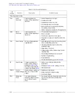
Sel
No
Terminal Description
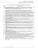
14
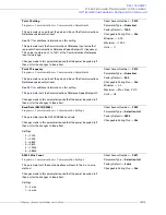
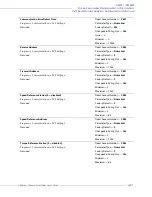
Motor Switching 1/ Motor Switching 2
— Activating combinations of discrete input terminals Motor Switching 1
and 2 allow for the selection of a V/f switching profile as listed below.
15
16
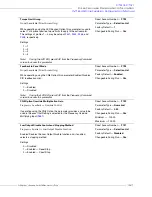
Torque Limit Switching 1/Torque Limit Switching 2
— Activating combinations of discrete input terminals Torque
Limit Switching 1 and 2 allow for the selection of a torque limit switching profile as listed below.
17
18
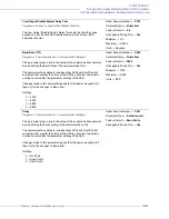
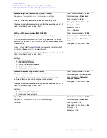
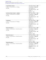
PID Control Off
— Connecting this terminal to CC turns off PID control.
19
Pattern 1
— Connecting this terminal to CC initiates the Pattern 1
Pattern Run
.
20
Pattern 2
— Connecting this terminal to CC initiates the Pattern 2
Pattern Run
.
21
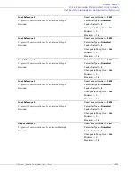
Pattern 3
— Connecting this terminal to CC initiates the Pattern 3
Pattern Run
.
22
Pattern 4
— Connecting this terminal to CC initiates the Pattern 4
Pattern Run
.
23
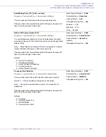
Pattern Continue
— Continues with the last
Pattern Run
from its stopping point when connected to CC.
24
Pattern Trigger
— This function is used to sequentially initiate each Preset Speed of a
Pattern Run
with each
connection to CC.
25
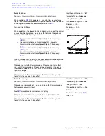
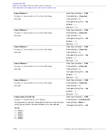
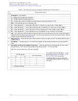
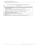
Forced Forward Jog
— This setting initiates a Forced Forward Jog when connected to CC. The Forced Forward Jog
command provides a forward-run signal so long as this terminal is connected to CC (the status of the F and R
terminals is ignored). Use
to set the Jog Frequency and use
to select the Jog Stop Method.
26
Forced Reverse Jog
— This setting initiates a Forced Reverse Jog when connected to CC. The Forced Reverse Jog
command provides a reverse-run signal so long as this terminal is connected to CC (the status of the F and R
terminals is ignored). Use
to set the Jog Frequency and use
to select the Jog Stop Method.
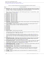
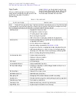
Table 8. (Continued) Discrete Input Terminal Assignment Selections and Descriptions.
Motor Switching Terminal
Motor Selection
#1
#2
0
0
1
0
1
2
1
0
3
1
1
4
1 = Terminal Activated
The 1 – 4 settings of the Motor Switching
selections are performed at parameters
–
F010.
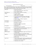
Torque Limit Switching Terminal
Torque Limit Selection
#1
#2
0
0
1
0
1
2
1
0
3
1
1
4
1 = Terminal Activated
The 1 – 4 settings of the torque limit
switching selections are performed at
parameters
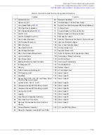
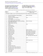
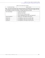
Input Terminal Assignments
Summary of Contents for W7 DN-57442-006
Page 1: ...ADJUSTABLE SPEED DRIVES W7 DN 57442 006 INSTALLATION OPERATION MANUAL June 2020 ...
Page 2: ......
Page 3: ...Document Number 57442 006 Date June 2020 W7 ASD Installation and Operation Manual ...
Page 4: ......
Page 60: ......
Page 221: ......

