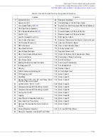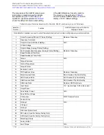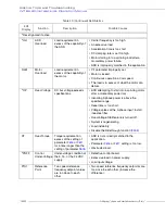
Direct Access Parameter Information
W7B ASD Installation & Operation Manual
https://www.toshiba.com/tic/
173
Sel
No
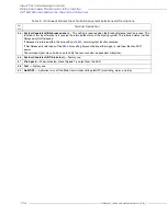
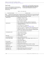
Terminal Description
51
Commercial Power/ASD Switching
— This function operates in conjunction with the Line Power Switching
frequency setting (
). An enabled selection at Program
Terminal Selection Parameters
Line Power
Switching (At) and this input terminal setting enables this function.
Once configured (including this terminal connection to CC), the frequency setting of Line Power Switching
(Hz)
establishes the speed at which the drive terminates its output and routes commercial power to the motor.
52
Frequency Priority
— Connecting this terminal to CC allows for the frequency control to be switched from the
frequency command source selected as Frequency Mode 1 to Frequency Mode 2. This function is enabled by setting
the Reference Priority Selection to Frequency Source Priority Switching and is located at Program
Fundamentals
Standard Mode Selection
Reference Priority Selection
Frequency Source Priority Switching.
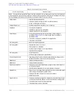
53
Terminal Frequency Priority
— Connecting this terminal to CC assigns command control to the VI/II Terminal and
overrides all other Control Terminal Strip input so long as the Command Mode is set to Use Control Terminal Strip.
54
Terminal Command Priority
— Connecting this terminal to CC overrides the FMOD setting and assigns speed
control to the Control Terminal Strip.
55
Parameter Editing Enable
— The LED Keypad system is unavailable at the time of this release.
56
Control Switch (Torque, Position)
— This function allows for a system change from speed to torque or position as
a function of the V/f setting when connected to CC.
57
Deviation Counter Clear
— This function resets the Error Counter when operating in the Position Control mode.
58
Position Control Forward Limit LS
— Connecting this terminal to CC will immediately stop the drive and hold its
position. If the connection remains the drive will time-out and trip. This function is normally used for over-travel
conditions.
59
Position Control Reverse Limit LS
— Connecting this terminal to CC will immediately stop the drive and hold its
position. If the connection remains the drive will time-out and trip. This function is normally used for over-travel
conditions.
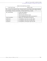
60
Light-Load High-Speed Operation Enable
— Activating this terminal sets the lower limit of an output frequency
range in which the Light-Load High-Speed function may be used (see
). The Light-Load High-Speed function
accelerates the output frequency of the ASD to the speed setting established in
for the duration of the
activation.
61
Lag Down Control Valid
— TBD.
62
Spare Excitation
— Connecting this terminal to CC applies an excitation current to the motor (holds shaft
stationary) for the duration of the connection.
63
System Consistent (BC: brake command)
— Not Used.
64
System Consistent (B: brake release)
— Activation initiates the brake release command. This setting requires that
another discrete input terminal be set to System Consistent (BA:Brake Answer) to complete the brake release
command and to convey the status of the braking system to the user or to a dependent subsystem.
Once the braking release function is initiated, the Brake Answer Waiting Time (
) begins to count down. Should
the count-down timer expire before the brake releases or before the Braking Answer is returned, fault E-11 will occur.
Otherwise, the brake releases the motor and normal motor operations resume.
The Braking Release function is primarily used at startup; but, may be used when the brake is applied while the
motor is running.
Table 8. (Continued) Discrete Input Terminal Assignment Selections and Descriptions.
Input Terminal Assignments
Summary of Contents for W7 DN-57442-006
Page 1: ...ADJUSTABLE SPEED DRIVES W7 DN 57442 006 INSTALLATION OPERATION MANUAL June 2020 ...
Page 2: ......
Page 3: ...Document Number 57442 006 Date June 2020 W7 ASD Installation and Operation Manual ...
Page 4: ......
Page 60: ......
Page 221: ......

