18
https://www.toshiba.com/tic/
Installation and Connections
W7B ASD Installation & Operation Manual
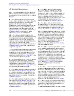
I/O Terminal Descriptions
Note:
The programmable terminal assignments
of the discrete input terminals may be accessed
and changed from their default settings as mapped
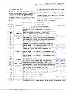
on
.
ST
— The default setting for this terminal is the
Standby mode controller. As the default setting, this
terminal must be activated for normal system
operation. The ST terminal is activated by
connecting CC to this terminal (Sink mode). When
deactivated, OFF is displayed at the Frequency
Command screen. This input terminal may be
programmed to any of the functions that are listed
in
Also, see ST Signal
Selection on
for more information.
RES
— The default setting for this terminal is
Reset. The RES terminal is activated by connecting
CC to this terminal (Sink mode). A momentary
connection to CC resets the ASD and any fault
indications from the display. Reset is effective when
faulted only. This input terminal may be
programmed to any of the functions that are listed
in
(see RES Input Terminal
Assignment on
F
— The default setting for this terminal is Forward
run command. The F terminal is activated by
connecting CC to this terminal (Sink mode). This
input terminal may be programmed to any of the
functions that are listed in
(see
F Input Terminal Assignment on
R
— The default setting for this terminal is Reverse
run command. The R terminal is activated by
connecting CC to this terminal (Sink mode). This
input terminal may be programmed to any of the
functions that are listed in
(see
R Input Terminal Assignment on
).
S1
— The default setting for this terminal is Preset
Speed Bit 1 (see
). The
S1 terminal is activated by connecting CC to this
terminal (Sink mode). This input terminal may be
programmed to any of the functions that are listed
in
S2
— The default setting for this terminal is Preset
Speed Bit 2 (see
). The
S2 terminal is activated by connecting CC to this
terminal (Sink mode). This input terminal may be
programmed to any of the functions that are listed
in
S3
— The default setting for this terminal is
Transformer Thermal Switch Monitor. The S3
terminal is activated by connecting CC to this
terminal (Sink mode). If the connection opens, the
drive will either stop running or stop running and
display an Emergency fault (depending on the
programming assigned to the terminal). This input
terminal may be programmed to any of the
functions that are listed in
.
S4
— The default setting for this terminal is
Emergency Off. The S4 terminal is activated by
connecting CC to this terminal (Sink mode). This
input terminal may be programmed to any of the
functions that are listed in
.
RR
— The default function assigned to this terminal
is the Frequency Mode 1 setting. The RR terminal
accepts
a 0 – 10 VDC input signal that is used to
control the function assigned to this terminal. This
input terminal may be programmed to control the
speed or torque of the motor via an amplitude
setting or regulate by setting a limit. The gain and
bias of this terminal may be adjusted for
application-specific suitability (see
).
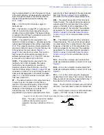
This terminal references CC.
RX
— The default function assigned to this terminal
is the Torque Command setting. The RX terminal
accepts a ±10 VDC input signal that is used to carry
out the function assigned to this terminal. This input
terminal may be programmed to raise or lower the
speed or torque of the motor via an amplitude
setting. This terminal may also be used to regulate
the speed or torque of a motor by setting a limit.
The gain and bias of this terminal may be adjusted
for application-specific suitability (see
–
depiction of the RX terminal. This terminal
references CC.
II
— The default function assigned to this terminal is
to carry out the Frequency Mode 2 speed control.
The function of the II input is to receive a 4 – 20 mA
input signal that controls a 0 – Maximum Frequency
output. This input terminal may be programmed to
control the speed or torque of the motor and may
not be used when using the VI input. The gain and
bias of this terminal may be adjusted for
application-specific suitability (see
).
VI
— The default function assigned to this terminal
is to carry out the Frequency Mode 2 speed control.
The function of the VI input is to receive a 0 – 10
VDC input signal that controls a
0 – Maximum Frequency output. This input terminal
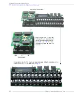
ST
RES
F
R
S1
S2
S3
S4
RR
RX
II
VI
Summary of Contents for W7 DN-57442-006
Page 1: ...ADJUSTABLE SPEED DRIVES W7 DN 57442 006 INSTALLATION OPERATION MANUAL June 2020 ...
Page 2: ......
Page 3: ...Document Number 57442 006 Date June 2020 W7 ASD Installation and Operation Manual ...
Page 4: ......
Page 60: ......
Page 221: ......

