22
https://www.toshiba.com/tic/
Installation and Connections
W7B ASD Installation & Operation Manual
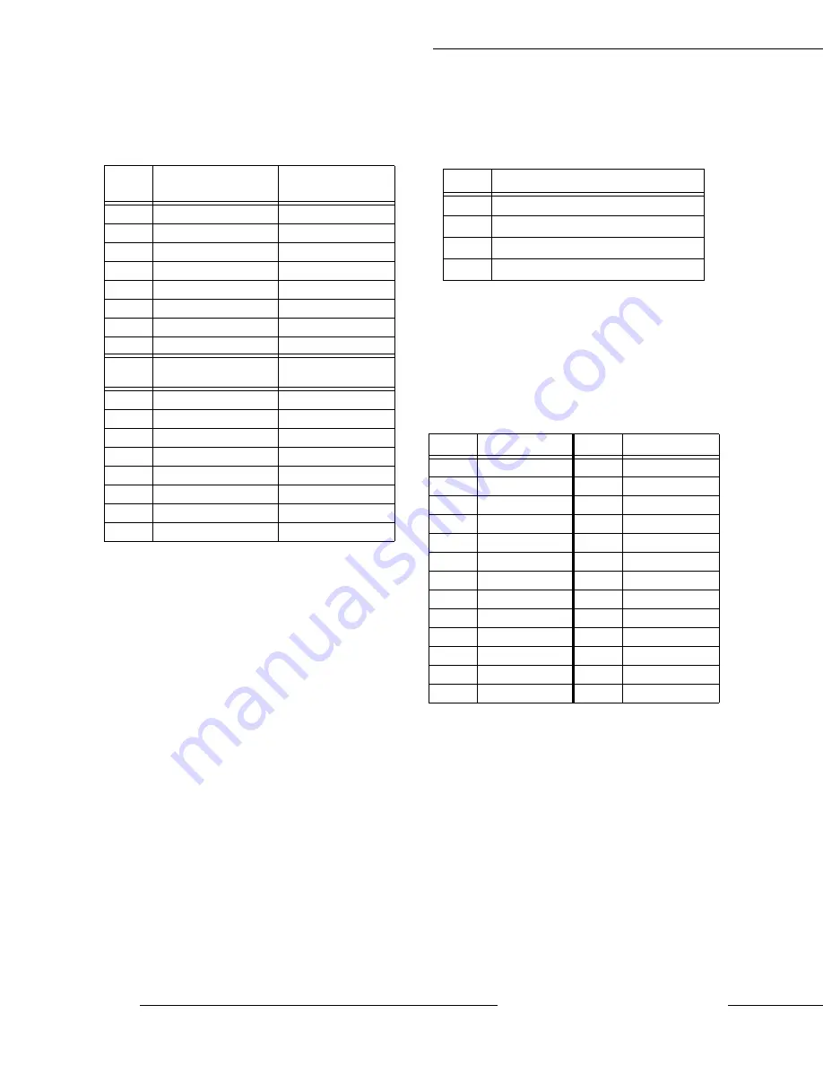
CNU1/1A and CNU2/2A Pinout
Control Board CNU1/1A and CNU2/2A pinout (RJ-
45 connectors).
CN3 Pinout
CN3 of the Control Board is used for 2-wire RS485
serial communications.
Note:
CNU2 or CNU3 may be used for RS485
communication — cannot use both simultaneously.
CN7 Pinout
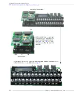
CN7 of the Control Board connects to CN7A of the
Terminal Board. Programmable terminals are listed
as their default settings.
Pin #
CNU1 Pinout
(Control Board)
CNU1A Pinout
(EOI)
1
P24
P24
2
Gnd
Gnd
3
Tx (-)
RXA
4
Rx (+)
TXA
5
Rx (-)
TXB
6
Tx (+)
RXB
7
RS232/RS485
CNU3 Pin-7
8
Gnd
Gnd
Pin #
CNU2 Pinout
(Control Board)
CNU2A Pinout
(EOI)
1
P24
P24
2
Gnd
Gnd
3
Rx
Tx
4
Gnd
Gnd
5
Tx
Rx
6
Gnd
Gnd
7
Open
Open
8
Gnd
Gnd
Pin #
CN3 Pinout (Controller PCBA)
1
RS485
2
RS485 Signal -
3
RS485 Signal Gnd
4
Shield
Pin #
Function
Pin #
Function
1
PP
14
II
2
FL
15
S1
3
VI
16
R
4
RR
17
S3
5
FM
18
S2
6
RX
19
N15
7
FP
20
S4
8
AM
21
P15
9
OUT1
22
P24
10
OUT2
23
CC
11
ST
24
CC
12
RES
25
CC
13
F
—
—
Summary of Contents for W7 DN-57442-006
Page 1: ...ADJUSTABLE SPEED DRIVES W7 DN 57442 006 INSTALLATION OPERATION MANUAL June 2020 ...
Page 2: ......
Page 3: ...Document Number 57442 006 Date June 2020 W7 ASD Installation and Operation Manual ...
Page 4: ......
Page 60: ......
Page 221: ......

