Direct Access Parameter Information
W7B ASD Installation & Operation Manual
172
https://www.toshiba.com/tic/
Sel
No
Terminal Description
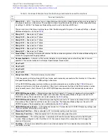
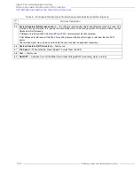
27
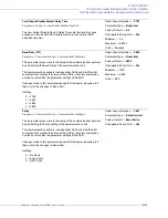
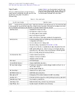
Binary Bit 0
— Bit 0 – 7 may be set up as a speed/torque control register. Speed/torque settings may be applied to
this group of terminals in binary form. The required number of input terminals should be set to the respective binary
bit settings (0 – MSB). The Frequency Mode setting must be set to Use Binary/BCD input.
The gain and bias of the binary input may be set from the following path: Program
Frequency Settings
Speed
Reference Setpoints
BIN (see
).
28
Binary Bit 1
— See selection 27 above.
29
Binary Bit 2
— See selection 27 above.
30
Binary Bit 3
— See selection 27 above.
31
Binary Bit 4
— See selection 27 above.
32
Binary Bit 5
— See selection 27 above.
33
Binary Bit 6
— See selection 27 above.
34
Binary Bit 7
— See selection 27 above.
35
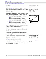
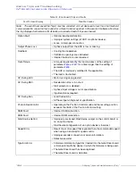
Forced Stop
— Activating this terminal terminates the Run command regardless of the Command Mode setting and
initiates the programmed stopping method.
36
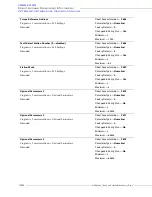
Damper Feedback
— Activation of this terminal indicates an open damper and enables the system for normal
operation. This terminal connects to a Damper Open/Damper Closed switch.
37
User Fault 1
38
User Fault 2
39
User Fault 3
40
User Fault 4
43
Binary Data Write
— This terminal serves two functions:
1) While operating in the Use Binary/BCD input mode, each momentary connection of this terminal to CC transfers
the speed/torque Binary Bit (0 – MSB) settings to the motor.
2) The UP/DOWN Frequency command will be saved during power down or reset by setting
to Store and
setting an input terminal to 43:binary Data Write. If the drive is running and the Binary Data Write terminal is active
when an event occurs (Fault, Power off), the UP/DOWN Frequency command will be restored upon power-up or
reset.
44
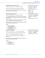
UP/DOWN Frequency (Up)
— Momentarily connecting this terminal to CC causes an increase in motor speed for
the duration of the connection until the Upper-Limit is reached. The Frequency Mode setting must be set to UP/
DOWN Frequency. The acceleration rate is determined by the
setting.
45
UP/DOWN Frequency (Down)
— Momentarily connecting this terminal to CC causes a decrease in motor speed for
the duration of the connection until the Lower-Limit is reached. The Frequency Mode setting must be set to UP/
DOWN Frequency. The deceleration rate is determined by the
setting.
46
UP/DOWN Frequency (Clear)
— Connecting this terminal to CC clears the last UP/DOWN Frequency settings (see
for additional information on this setting).
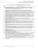
47
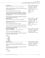
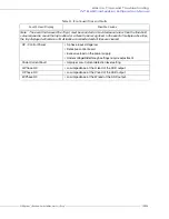
Momentary Push Run
— When connected to CC, this terminal setting starts the motor.
48
Momentary Push Stop
— When connected to CC, this terminal setting stops the motor.
49
Forward/Reverse
— This setting operates in conjunction with another terminal being set to the Run/Stop (50)
function. When configured to Run (Run/Stop to CC), the make or break of this connection to CC changes the
direction of the motor.
50
Run/Stop
— This terminal enables the motor to run when connected to CC and disables the motor when the
connection is broken.
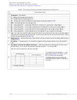
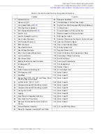
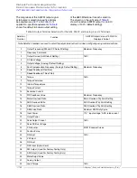
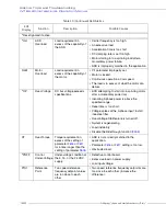
Table 8. (Continued) Discrete Input Terminal Assignment Selections and Descriptions.
Input Terminal Assignments
Summary of Contents for W7 DN-57442-006
Page 1: ...ADJUSTABLE SPEED DRIVES W7 DN 57442 006 INSTALLATION OPERATION MANUAL June 2020 ...
Page 2: ......
Page 3: ...Document Number 57442 006 Date June 2020 W7 ASD Installation and Operation Manual ...
Page 4: ......
Page 60: ......
Page 221: ......


