14
https://www.toshiba.com/tic/
Installation and Connections
W7B ASD Installation & Operation Manual
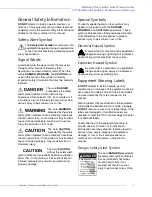
the TIC Customer Support Center or the process
controller manufacturer for additional information
about compatibility and signal isolation).
Use caution when setting the output frequency.
Over-speeding a motor decreases its ability to
deliver torque and may result in damage to the
motor and/or the driven equipment.
All W7B ASDs are equipped with internal DC bus
fuses. However, not all W7B ASDs are equipped
with internal primary power input fuses (HP-
dependent).
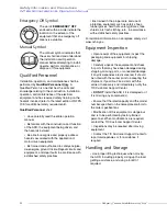
Mounting the ASD
Install the unit securely in a well-ventilated area that
is out of direct sunlight using the mounting holes on
the rear of the ASD.
This equipment is to be used in permanent
installations only.
The ambient temperature rating for the W7B ASD is
from 14° to 104° F (-10° to 40° C). The process of
converting AC to DC, and then back to AC
produces heat. During normal ASD operation, up to
5% of the input energy to the ASD may be
dissipated as heat. If installing the ASD in a
cabinet, ensure that there is adequate ventilation.
DO NOT
operate the ASD with the enclosure door
open or removed and ensure that the ventilation
openings are not obstructed.
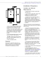
ASDs produce high-frequency noise — steps must
be taken during installation to avoid the negative
effects of noise. Listed below are some examples of
measures that will help to combat noise problems.
•
Separate the input and output power
conductors of the main circuit.
DO NOT
install the input and output wires in the
same duct or in parallel with each other, and
DO NOT
bind them together.
•
DO NOT
install the input or output power
conductors of the main circuit and the wires
of the control circuit in the same duct or in
parallel with each other, and
DO NOT
bind
them together.
•
Use shielded wires or twisted wires for the
control circuits.
•
Ensure that the grounding terminals (G/E)
of the ASD are securely connected to
ground.
•
Connect a surge suppressor to every
electromagnetic contactor and every relay
installed near the ASD.
•
Install noise filters as required.
Connecting the ASD
Refer to the section titled
and the section titled
before attempting to
connect the ASD and the motor to electrical power.
System Grounding
Proper grounding helps to prevent electrical shock
and to reduce electrical noise. The ASD is designed
to be grounded in accordance with Article 250 of
the NEC or Section 10/Part One of the Canadian
Electrical Code
(CEC).
The grounding conductor shall be sized in
accordance with Article 250-122 of the NEC or Part
One-Table 6 of the CEC.
— T h e M e t a l O f C o n d u i t I s
N o t A n A c c e p t a b l e G r o u n d —
The input power, output power, and control lines of
the system shall be run in separate metal conduits
and each shall have its own ground conductor.
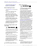
Power Connections
Connect the 3-phase input power to the input
terminals of the ASD at L1/R, L2/S, and L3/T.
Connect the output terminals T1/U, T2/V, and T3/W
of the ASD to the motor.
The input and output conductors and terminal lugs
used shall be in accordance with the specifications
listed in the section titled
.
An inductor may be connected across terminals PA
and PO to provide additional filtering. When not
used, a jumper must be connected across these
terminals (see
CAUTION
DANGER
DANGER
Summary of Contents for W7 DN-57442-006
Page 1: ...ADJUSTABLE SPEED DRIVES W7 DN 57442 006 INSTALLATION OPERATION MANUAL June 2020 ...
Page 2: ......
Page 3: ...Document Number 57442 006 Date June 2020 W7 ASD Installation and Operation Manual ...
Page 4: ......
Page 60: ......
Page 221: ......


