background image

– 52 –

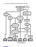
9-4-1. How to Check the P.C. Board

(1) Operating precautions

1) When removing the front panel or the P.C.

board, be sure to shut off the power supply.

2) When removing the P.C. board, hold the edge

of the P.C. board and do not apply force to the
parts.

3) When connecting or disconnecting the con-

nectors on the P.C. board, hold the whole
housing.  Do not pull at the lead wire.

(

2) Inspection procedures

1) When a P.C. board is judged to be defective,

check for disconnection, burning, or discolora-
tion of the copper foil pattern or this P.C.
board.

2) The P.C. board consists of the following 2

parts

a. Main P.C. board part:

Power relay, indoor fan motor drive circuit
and control circuit, C.P.U. and peripheral
circuits, buzzer drive circuit and buzzer.

b. Infrared rays receive and indication

parts:

Infrared rays receive unit and LED.

Summary of Contents for ZZ RAS-13YK-HX

Page 1: ...SERVICE MANUAL FILE NO DAS SM 00 003 AIR CONDITIONER SUPPLEMENT SPLIT WALL TYPE RAS 10YKH E RAS 10YAH E RAS 13YKH E RAS 13YAH E RAS 10YKH ES RAS 10YAH ES RAS 13YKH ES RAS 13YAH ES ...

Page 2: ... WIRING DIAGRAM 9 4 SPECIFICATIONS OF ELECTRICAL PARTS 11 5 REFRIGERANT CYCLE DIAGRAM 13 6 CONTROL BLOCK DIAGRAM 17 7 OPERATION DESCRIPTIONS 18 8 INSTALLATION PROCEDURE 27 9 TROUBLESHOOTING CHART 41 10 PART REPLACEMENT 57 11 EXPLODED VIEWS AND PARTS LIST 62 ...

Page 3: ... mm 6 35 Connection type Flare connection Maximum length of one way m 2 10 15 Interconnection pipe Maximum height difference Indoor unit Outdoor unit m 5 6 Condensate drain pipe Outer diameter mm 16 INDOOR UNIT RAS 10YKH E RAS 13YKH E Height mm 265 Width mm 790 Dimensions Depth mm 189 Net weight kg 8 Evaporator type Finned tube Indoor fan type Cross flow fan High fan m h 600 650 Medium fan m h 500...

Page 4: ...onnection Liquid side size mm 6 35 Connection type Flare connection Maximum length of one way m 2 10 15 Interconnection pipe Maximum height difference Indoor unit Outdoor unit m 5 6 Condensate drain pipe Outer diameter mm 16 INDOOR UNIT RAS 10YKH ES RAS 13YKH ES Height mm 265 Width mm 790 Dimensions Depth mm 189 Net weight kg 8 Evaporator type Finned tube Indoor fan type Cross flow fan High fan m ...

Page 5: ...nal refrigerant required This air conditioner accepts a connection piping length of up to 10m and a head of up to 5m There is no need to add the refrigerant as long as the total length of the connection piping is up to 10m RAS 13YKH E RAS 13YKH ES No additional refrigerant required This air conditioner accepts a connection piping length of up to 15m and a head of up to 6m There is no need to add t...

Page 6: ...are Ø9 52 Flare Ø12 7 for 13YKH E only Hanger 659 65 5 326 450 65 5 For stud bolt Ø8 Ø10 For stud bolt Ø6 Hanger Minimum distance to wall Minimum distance to ceiling 265 178 5 Knock out system Front panel Back body 20 20 37 40 5 60 5 790 126 269 319 76 Center line Installation plate outline Hanger Hanger 40 5 3 5 Hanger Minimum distance to wall 17 20 46 120 or more 120 or more 66 or more 2 5 Conne...

Page 7: ...10 50 36 25 216 230 Ø11x14 Hole Ø6 Hole Handle 11 525 530 5 268 Fan guard Ø420 TOSHIBA 770 59 89 200 11 12 Electric parts cover Z 54 62 Service port 250 Z View 600 45 or more Inlet port 600 or more Minimum distance of the wall 4 Ø11x14 Long holes For anchor bolt Ø8 Ø10 400 or more Outlet port Center port 230 100 or more Inlet port Visible outline of the product A Detail Drawing Mounting dimension ...

Page 8: ...00 or more 600 or more Installation dimension 600 Air inlet Air outlet 8 Ø6 hole for fixing outdoor unit Liquid side Flare Ø6 35 Gas side Flare Ø12 7 for 13YAH E Flare Ø9 52 for 13YAH ES 120 Ø11x14 hole Ø6 hole R10 600 Detail Drawing 50 36 A A 6 Ø11x14 hole for Ø8 Ø10 anchor bolt 600 100 130 780 90 59 27 Fan guard Ø420 Z View Z 4xØ11x14 Long holes for Ø8 Ø10 anchor bolt ...

Page 9: ...L BLOCK INDOOR TERMINAL BLOCK THERMO SENSOR TA AC FAN MOTOR HEAT EXCHANGER SENSOR TC BROWN RED WHITE YELLOW BLUE BLACK GRAY PINK ORANGE GREEN YELLOW BRW RED WHI YEL BLU BLK GRY PNK ORN GRN YEL COLOR IDENTIFICATION VARISTOR VARISTOR 1 9 8 7 6 5 4 3 2 1 9 8 7 6 5 9 8 7 6 5 4 4 3 3 2 2 1 1 2 2 1 SG01 DSA 1 2 3 5 3 1 1 2 3 YEL BLK BLK BRW PNK WHI 1 3 3 2 1 4 3 2 1 4 COMPRESSOR BLU PNK BLK WHI BLU BLU ...

Page 10: ...AL BLOCK THERMO SENSOR TA AC FAN MOTOR HEAT EXCHANGER SENSOR TC BROWN RED WHITE YELLOW BLUE BLACK GRAY PINK ORANGE GREEN YELLOW BRW RED WHI YEL BLU BLK GRY PNK ORN GRN YEL COLOR IDENTIFICATION VARISTOR 1 9 8 7 6 5 4 3 2 1 9 8 7 6 5 9 8 7 6 5 4 4 3 3 2 2 1 1 2 2 1 SG01 DSA 1 2 3 5 3 1 1 2 3 YEL BLK BLK BRW PNK WHI 1 3 3 2 1 4 3 2 1 4 COMPRESSOR BLU PNK BLK WHI BLU BLU BLU BLU BLU OUTDOOR TERMINAL B...

Page 11: ... Power relay Common relay RY01 RY02 DI1U Coil DC 12V 75mA Rated AC 250V 20A 6 Heat exchanger sensor TC sensor Microprocessor 10kW at 25 C 7 Line filter L01 SS11V 06180 18mH AC 0 6A 8 Diode DB01 D3SBA60 4A 600V 9 Capacitor C02 CEAUF2W101M20 100mF 450V 10 Fuse F01 MT3 T3 15A 250V 11 Relay RY03 Ry04 for outdoor fan motor solenoid coil AJQ1341 Coil DC 12V 33Ma Rated 1A AC 250V 12 Power supply IC IC01 ...

Page 12: ...lack RAS 10YAH E RAS 10YAH ES UE6 21SJ5P Winding resistance W at 20 C 370 370 Output Rated 28W 6poles 1phase 220 240V 50Hz Red Black White Black 2 Fan motor for outdoor RAS 13YAH E RAS 13YAH ES AF 230 28P Winding resistance W at 20 C 198 160 RAS 10YAH E RAS 10YAH ES SK 50FMP1 5U1 AC 500V 1 5mF 3 Running capacitor for fan motor RAS 13YAH E RAS 13YAH ES SK 50FMP1 5U2 AC 500V 1 5mF RAS 10YAH E RAS 10...

Page 13: ...ooling Heating Mark means check points of Gas Leak O D 9 52mm O D 6 35mm Cooling Heating Packed valve ø9 52 Packed valve ø6 35 0 39m Connecting pipe ø9 52 0 49m Connecting pipe ø6 35 T P Refrigerant R 22 0 74kg Ambient temp conditions DB WB C 50Hz Standard pressure P kg cm G Surface temp of heat exchanger interchanging pipe T C Fan speed indoor Indoor Outdoor Standard 15 0 40 0 High 21 7 6 High te...

Page 14: ... means check points of Gas Leak O D 12 7mm O D 6 35mm Cooling Heating Packed valve ø12 7 Packed valve ø6 35 0 49m Connecting pipe ø12 7 0 39m Connecting pipe ø6 35 T P Refrigerant R 22 0 88kg Capillary tube ø1 7x400 Capillary tube ø0 6x1500 Ambient temp conditions DB WB C 50Hz Standard pressure P kg cm G Surface temp of heat exchanger interchanging pipe T C Fan speed indoor Indoor Outdoor Standard...

Page 15: ... points of Gas Leak O D 9 52mm O D 6 35mm Cooling Heating Packed valve ø9 52 Packed valve ø6 35 0 39m Connecting pipe ø9 52 0 49m Connecting pipe ø6 35 T P Refrigerant R 410A 0 69kg Capillary tube ø1 2x400 Muffler Muffler Ambient temp conditions DB WB C 50Hz Standard pressure P MPaG Surface temp of heat exchanger interchanging pipe T C Fan speed indoor Indoor Outdoor Standard 2 5 43 0 High 20 7 6 ...

Page 16: ...oling Gas container connection Reinstall etc Packed valve ø9 52 Packed valve ø6 35 Note Maximum pipe length is 15m Maximum pipe head is 6m 0 49m Connecting pipe ø9 52 0 39m Connecting pipe ø6 35 T P Refrigerant R 410A 0 80kg Capillary tube ø1 2x1200 Muffler Ambient temp conditions DB WB C 50Hz Standard pressure P MPaG Surface temp of heat exchanger interchanging pipe T C Fan speed indoor Indoor Ou...

Page 17: ...O COOL DRY HEAT FAN ONLY Operation START STOP Relay Driver Louver Driver Clock Frequency Oscillator Circuit Heat Exchanger Sensor Infrared Rays Initializing Circuit C P U Main Unit Control Panel AC 220 230 240V 50Hz Remote Control Operation Display Timer Display ECONO Sign Display PRE DEF Sign Display Indoor Fan Motor Louver ON OFF Signal 4 Way Valve ON OFF Signal Outdoor Fan ON OFF Signal Compres...

Page 18: ...on to ener gize the outdoor unit and a cool operation is carried out 1 When the FAN is set to AUTO the indoor fan motor operates as shown in Fig 7 2 2 2 When the FAN is set to LOW MED or HIGH the indoor fan motor operates with a constant in volume as listed in Table 7 1 1 Room temp Set temp MED LOW LOW LOW continuous 4 3 2 1 0 RY01 OFF Set temp Manual FAN According to the set position HIGH AUTO HI...

Page 19: ... AUTO position 2 The pattern of operation depending on the relation between room temperature and set temperature is shown below Room temp Set temp 1 Set temp Compressor Outdoor fan Indoor fan L S L S L L L S L L ON ON ON ON OFF OFF OFF Super Low Fig 7 3 2 7 4 HEAT Operation MODE of the remote control HEAT 1 Relays compressor 4 way valve outdoor fan and operation display are controlled as shown in ...

Page 20: ...he details are in 7 10 7 5 AUTO Operation MODE of the remote control AUTO 1 One of the 3 modes Cooling Fan only and Heating is selected according to room tempera ture at which operation is to start as shown in Fig 7 5 1 The Fan mode will continue until room temperature reaches a level at which another mode is selected 7 5 1 Temporary Auto When the TEMPORARY button is pushed 1 sec the set temperatu...

Page 21: ... 6 2 2 Fan speed LOW 7 7 Current Limit Control The microprocessor detects the input current so as to prevent it exceeds a specified value by means of controlling the outdoor fan control as described in 1 and 2 1 Current limit control Cooling Control is performed as shown below by detect ing the compressor operation current with a current sensor C T RAS 10YKH E RAS 13YKH E RAS 10YKH ES RAS 13YKH ES...

Page 22: ...7 9 1 and 7 9 2 RAS 10YKH E RAS 10YKH ES Compressor Less than 5 C continues for 5 minutes OFF ON Outdoor fan 7 Heat exchanger temperature 5 C Fig 7 9 2 According to the set position Indoor fan speed 35 32 30 20 Heat exchanger temperature C U L Ultra Low Room temp Set temp S L Super Low Room temp Set temp OFF According to the set position Indoor fan speed 30 25 20 Heat exchanger temperature C U L U...

Page 23: ...ation time is 10 minutes 7 11 3 Ending Condition at Defrost Operation 1 When the compressor current becomes 7 5A or more during defrost operation the defrost opera tion stops and the heat operation restarts The current sensor detects the compressor current 2 The defrost operation continues for at most 6 minutes or 10 minutes DEFROST LAMP During defrost operation the PRE DEF lamp is on and the indo...

Page 24: ...tings can be carried out OPERATION Push the TEMPORARY button continuously more than three seconds MOTION Operating The green light is lit The system stops to operate The green light is turned off about three seconds after The unit beeps three times The system stops If the system is not required to stop at this time use the remote control and to restart TEMPORARY 0 3S OPERATION Push the TEMPORARY b...

Page 25: ...eed as follows Repeat the setting procedure the unit will acknowl edge the instruction and bleep three times When the system is stand by not running When the system is operating During subsequent operation the green light is lighting The system will now be required to manually restart with the remote control after the main supply is turned off Cancellation is carried out 7 12 3 In Case of Power Fa...

Page 26: ...NOT PRESS OR FIX THE CORD AND CABLES FIRMLY WITH STAPLES etc DO NOT USE THE EXTENSION CABLE FOR POWER SUPPLY CORD OR INTER CONNECTING CABLE NEVER EXECUTE THE CONNECTION OF WIRING WITH OTHER METHOD THAN THE APPROVED ONE OTHERWISE OVERHEAT SMOKE OR FIRE MAY BE GENERATED BY CONTACT ERROR TURN OFF MAIN POWER SUPPLY AND BREAKER BEFORE ATTEMPTING ANY ELECTRICAL WORK MAKE SURE ALL POWER SWITCHES AND BREA...

Page 27: ... install in a place that can increase the vibration of the unit Do not install in a place that can amplify the noise level of the unit or where noise and discharged air might disturb user s neighbors To avoid personal injury be careful when handling parts with sharp edges Please read the installation manual carefully before installing the unit It contains further important instructions for proper ...

Page 28: ...3 Batteries Cover 6 mm thick heat resisting polyethylene foam Bottom Rear Right Rear left Left Cut the piping hole sloped slightly Wall 120 mm or more For the rear left and left piping Do not allow the drain hose to get slack Make sure to run the drain hose sloped downward The auxiliary piping can be connected the left rear left rear right or bottom Insulation of refrigerant pipes insulates the pi...

Page 29: ...ple to the bottom plate of the outdoor unit before installing it The drain nipple is located as shown above Drainage Drain hose sold separately or one on the market 7 Drain nipple Bottom plate ø25 Fig 8 3 2 Install the provided drain nipple in the hole of the bottom plate of the outdoor unit See the above figure Perform proper drainage processing using a drain hose sold separately or one on the ma...

Page 30: ...y Part No Name of parts Q ty Installation plate x 1 Wireless remote control x 1 Remote control holder x 1 Pan head wood screw ø3 1 x 16 x 2 Batteries x 2 Mounting screw ø4x 25 x 6 Drain nipple x 1 This model is not equipped with an extension drain hose Option For the extension drain hose use an optionally available RB 821SW or commercially available one Name Installation manual Owner s manual Othe...

Page 31: ... to prevent image disturbances or noise interference The location of the remote control should be determined as shown below Fig 8 4 1 Top view Indoor unit 5 m 5m 45 45 Remote control Reception range Axial distance Remote control Reception range 7m Side view Indoor unit 7m 7 5 8 4 1 Cutting a Hole and Mounting Installation Plate Cutting a hole When installing the refrigerant pipes from the rear Fig...

Page 32: ...g Attach power supply plug with power cord and plug it into wall outlet An approved power supply cord and plug must be used NOTE Perform wiring works so as to allow a generous wiring capacity No adjustment is necessary When the installation plate is directly mounted on the wall 1 Securely fit the installation plate onto the wall by screwing it in the upper and lower parts to hook up the indoor uni...

Page 33: ... Power supply cord Terminal block Earth line Screw Screw L N Fig 8 4 7 Stripping length of power cord NOTE Use standard wire only Wire type More than H05 RN F Fig 8 4 8 Earth line 40mm 10mm 10mm 30mm L N Fig 8 4 5 As the colors of the flexible cord of this appliance may not correspond with the colored markings to identify terminals in your plug as follows Connect BROWN colored core to plug termina...

Page 34: ...emove the front cabinet When the panel is removed and mounted again take the following actions After fastening the two screws one each at the left and right of the air outlet be sure to push the upper center Q right end R left end S and the lower center T of the air outlet and confirm that no gap is left between the front cabinet and the rear plate If cooling dry operation is made without pushing ...

Page 35: ...nnecting cable Installation plate Auxiliary pipes Carefully arrange pipes so that any pipe does not stick out of the rear plate of the indoor unit Carefully connect the auxiliary pipes and connecting pipes to each other and cut off the insulating tape wound on the connecting pipe to avoid double taping at the joint moreover seal the joint with the vinyl tape etc Since dewing results in a machine t...

Page 36: ...8 5 Outdoor Unit KInstallation place A place which provides the spaces around the outdoor unit as shown in the diagram in page 7 A place which can bear the weight of the outdoor unit and does not allow an increase in noise level and vibration A place where the operation noise and discharged air do not disturb your neighbors A place which is not exposed to a strong wind A place free of a leakage of...

Page 37: ...e pipe with a pipe cutter 90 Obliquity Roughness Warp Half union or packed valve Flare nut Externally threaded side Internally threaded side Use a wrench to secure Use a torque wrench to tighten Fig 8 5 4 Fig 8 5 2 2 Insert a flare nut into the pipe and flare the pipe Outer dia 6 35mm 9 52mm 12 7mm A mm R22 Imperial Rigid 1 0 1 5 0 5 1 0 1 0 1 5 0 5 1 0 1 5 2 0 0 5 1 1 A mm R410A Imperial Rigid 1 ...

Page 38: ... 6 Open the stems of packed valves A and B all the way 7 Securely tighten the stem cap to each of the packed valve stems VP Outdoor unit Charge hose B Service port Packed valve A B C D Gas Ø9 52 Liquid Ø6 35 Indoor unit Lo Hi High pressure side handle Pressure gage Manifold valve Low pressure side handle Charge hose A Fig 8 5 5 CAUTION KEEP IMPORTANT 4 POINTS FOR INSTALLATION PIPING WORK 1 Take aw...

Page 39: ...ndoor unit to outdoor unit size of wire and wiring method etc Every wire must be connected firmly NOTE Wipe type More than H05 RN F 70mm 4 3 2 1 1 2 3 4 10mm 10mm 60mm Connecting cable Screw Terminal block Terminal screw Cord clamp Earth line 8 6 Others 8 6 1 Gas Leak Test Fig 8 6 1 Check the flare nut connections valve stem cap connections and service cap connections for gas leak with a leak dete...

Page 40: ...so causes the lamp to blink 2 Fan speed remains unchanged in the dry mode Fan speed is automatically controlled in the dry mode 3 The compressor will not switch on or off even when the thermo control is operated in the dry operation In the dry mode the compressor goes on and off at regular intervals independent of the thermo control 4 The PRE DEF lamp comes on when the heating operation is started...

Page 41: ...control operation Turn off the power once turn it on again and try to operate the remote control again Remote control is possible OK The compressor operates The outdoor part is defective outdoor fan motor The outdoor fan does not rotate The compressor does not operate The inside part is defective Block display Description A OPERATION display blinking 1 Hz Power failure when power is ON B OPERATION...

Page 42: ...ON OFFTIMER C MODE FAN TEMP TEMP START STOP TIMER WH E1BE ECONO ON OFF RSV CNL ACL CHK FAN SET MODE AUTO AUTO COOL DRY HEAT FANONLY AUTO LOW MED HIGH 1 2 3 4 5 6 1 4 6 2 3 Caution of servicing check 1 After finished servicing check push START STOP button and confirm to change main body and remote control on normal operation mode 2 After finished servicing check disconnect plug or turned off circui...

Page 43: ...ff Indicated when detected abnormal Replace P C board Cable connectio n Therm al fuse Refrigera nt system 1 Wrong wiring or disconnection of connective cable 2 Thermal fuse cut off All off Indicated when detected abnormal 1 Check connective cable correct if wiring is wrong 2 Check thermal fuse and Terminal blocks 3 If it is OK check P C board 1 Overload relay or thermostat for compressor break All...

Page 44: ...ng cable is defective Replace the thermal fuse set Check connection Is the indication voltage DC12V or 5V of main PC board correct Is the voltage across C02 measured DC310V 340V Refer to the paragraph Pre check or defective circuit before power PC board block Shut off the power supply once and turn it on again after dis connecting the motor connector CN10 Motor is defective YES SW transformer T01 ...

Page 45: ... Indoor terminal block To the paragraph of No Power turns on Does the OPERATION lamp blink YES NO Connect the AC Power supply Return the wiring of the power relay is returned to the normal procedure Is it wired as shown in Figure below YES NO RY01 RY02 Brown N L Power terminal block T02 P C board Blue White Black 1 2 3 4 Indoor terminal block RAS 10YAH E RAS 10YAH ES RAS 13YKH E RAS 13YKH ES ...

Page 46: ...connection between indoor and outdoor units correct Check items as following procedure in 9 3 4 9 3 5 9 3 6 Replace the P C board See Power can not be turned on Relays RY01 RY02 or IC31 or IC30 is failure Correct cabling between indoor and outdoor units NO NO NO NO YES YES YES YES See Power can not be turned on Is AC 220 240V supplied between terminal block 1 2 9 3 3 Outdoor Unit does not Operate ...

Page 47: ...winding normal Check the winding resistor Is the capacitor for compressor normal Is the overload relay normal Does the compressor start Compressor starts but it stops after a while Cables between indoor and outdoor units are defective Re wire or replace the defective cords Compressor is defective Capacitor is defective Overload relay is defective Compressor is defective Correct cabling between ind...

Page 48: ...inding normal Check the winding resistance Is the capacitor for compressor normal Outdoor fan motor is defective Cables between indoor and outdoor units are defective Outdoor fan motor is defective Correct cabling between indoor and outdoor units NO NO NO NO YES YES YES YES Are all the cords for outdoor fan motor normal Correct the wire or replace the defective cords Capacitor for outdoor fan moto...

Page 49: ...tdoor units correct Replace the P C board See Power can not be turned on NO NO NO NO YES YES YES YES 4 way valve is defective Cables between indoor and outdoor units are defective Correct cabling between indoor and outdoor units NO NO YES YES Is the wiring of solenoid coil for 4 way valve normal Is the voltage across the terminal 2 3 220 240 V See Power can not be turned on Solenoid coil is defect...

Page 50: ...ecting Does the cross flow fan rotate normally Is the rotation signal DC 5V 0V output between 4 blue lead wire and 2 black lead wire of the motor connector CN10 when rotating the cross flow fan by hand in no operating status 2 pulses one turn Turn on the power supply Repair the bearing of the fan NO YES YES NO NO YES YES YES NO Turn the power supply Shut off the power supply once NO NO Does connec...

Page 51: ...luorescent light Is operation possible when the transmitter is moved nearer to the infrared signal receiver of the air conditioner Battery life Can any signal tone be heard in a transistor radio when transmitting within 5cm distance from the radio Does the transmission indicator light Is there any beep and operation Short circuit the metal terminal at the side of the battery compartment all clear ...

Page 52: ... P C board hold the whole housing Do not pull at the lead wire 2 Inspection procedures 1 When a P C board is judged to be defective check for disconnection burning or discolora tion of the copper foil pattern or this P C board 2 The P C board consists of the following 2 parts a Main P C board part Power relay indoor fan motor drive circuit and control circuit C P U and peripheral circuits buzzer d...

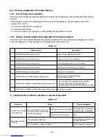
Page 53: ... restart delay timer is shortened 1 All indicators light for 3 sec 2 Indicators do not indicate normally after approximate 3 sec ü ý þ Defective indicator or poor housing assembly CN13 5 Make the operation status by pressing once the START STOP button 1 The time of the restart delay timer is shortened 2 Cool operation 3 Air volume AUTO 4 Make the setting temperature lower enough than room temperat...

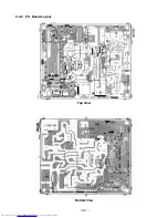
Page 54: ... 54 9 4 2 P C Board Layout Bottom View Top View ...

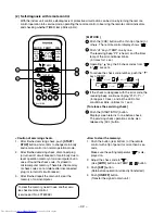
Page 55: ...imer short mode 2 Push the CNL button while keeping CHK button pushed In this case the check mode is released and the timer short mode is waited The status is kept even if CHK and CNL buttons are released 3 Pushing START STOP buttons sends operation code timer short code 4 The timer short mode is released by only a transmission Therefore repeat steps from 2 to perform the timer short mode again Fi...

Page 56: ...of the air outlet 4 Check the gap between the front panel and the main unit If cooling or drying operation is performed without pressing the center of the air outlet the surface of the front panel may be covered with frost and have a dew drop R Electrical part assembly 1 Perform the process Q above 2 Remove the electrical part cover by pressing the nail located on upper portion of the electrical p...

Page 57: ...w fixing it then remove the right side of the end plate from the rib fixing the main unit by sliding the heat exchanger slightly to the right side V Cross flow fan 1 Perform the process S 2 Loosen the set screw of the cross flow fan 3 Remove the screw fixing the shaft bearing base 4 Lift slightly up the left side of the heat exchanger and pull the shaft bearing base out left downwards When assembl...

Page 58: ... panel Remove the two fixing screws Ø4 x 14 l 3 Remove the electrical part base Replace the thermal fuse terminal block power cord microcomputer ass y and the power supply P C board ass y R Thermal fuse replacement 1 Perform the process Q above 2 Remove terminal cover Up Down 3 Disconnect the terminal blocks connected with the connecting cable and the power cord from base E parts by removing the s...

Page 59: ...asher Pull the front lower portion toward you and remove it pulling out upward R Capacitor for compressor 1 Remove the fixing screw the capacitor band 1 ST2T Ø4 x 8 l 2 Remove the cable connected to the terminal Refer to Specifications of Electrical Parts in page 11 S Capacitor for fan motor 1 Remove the fixing screw of the capacitor band 1 ST2T Ø4 x 8 l 2 Remove the cable connected to the termina...

Page 60: ...process Q above 1 Remove the fixing screw of the capacitor band 1 ST2T Ø4 x 8 l 2 Remove the cable connected to the terminal S Capacitor for fan motor 1 Perform the process Q above 1 Remove the fixing screw 1 ST2T Ø4 x 8 l 2 Remove the cable connected to the terminal T Overload relay 1 Perform the process Q above 2 Remove Fastons of leads 3 Remove the fixing screw 1 ST2T Ø4 x 10 l 4 Pull OL Holder...

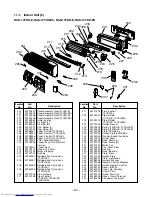
Page 61: ...e Terminal 3P AC 300V 20A 403 43T69004 Sensor Heat Exchanger 10kΩ 25 C 404 43T69005 Sensor Thermostat 10kΩ 25 C 405 43T60061 Fuse Set Thermal 77 C Location Part Description No No 406 43T69051 P C Board Assembly MCC 772 13YKH E 13YKH ES 406 43T69052 P C Board Assembly MCC 772 10YKH E 10YKH ES 406 43T69031 P C Board Assembly WRS LED MCC 766 407 43T61001 Base E Parts ABS Black UL94 5V ...

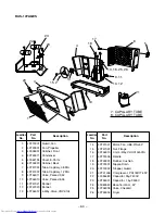
Page 62: ...S 216 43T47006 Pipe Delivery 217 43T47005 Pipe Suction 10YKH E 10YKH ES 13YKH ES Location Part Description No No 217 43T47016 Pipe Suction 13YKH E 218 43T49007 Pipe Shield 10YKH E 10YKH ES 218 43T49010 Pipe Shield 13YKH E 13YKH ES 219 43T19003 Holder Sensor 220 43T49003 Spring 10YKH E 10YKH ES 220 43T49009 Spring 13YKH E 13YKH ES 221 43T49028 Plate EVA SEAL 222 43T49023 Holder Plate EVA SEAL 223 4...

Page 63: ...7001 Nut Flat washer 27 43T45003 Dryer Location Part Description No No 1 43T19001 Guard Fan 2 43T20001 Fan Propeller 3 43005037 Cabinet Front 4 43T43001 Condenser 10YAH E 5 43062194 Cover E Parts 6 43T00320 Cabinet Back 7 43T47014 Tube Capillary 8 43T46017 Valve Packed 9 52 9 43T47021 Bonnet 10 43T46016 Valve Packed 6 35 11 43T47020 Bonnet 12 43T46003 4 Way Valve VH7100D 13 43T21001 Motor Fan UE6 ...

Page 64: ...apillary 1 2DIA 9 43T46011 Valve Packed 9 52 10 43T46010 Valve Packed 6 35 11 43T47021 Bonnet 12 43T47020 Bonnet 13 43T46012 4 Way Valve VHV 0104 Location Part Description No No 14 43T21001 Motor Fan UE6 21SJ5P 15 43T47001 Nut Flange 16 43T46013 Coil 4 Way VHV 01AI501A 17 43T19005 Handle 18 43T49001 Rubber Cushion 19 43T79001 Nipple Drain 20 43T19002 Stopper Guard 21 43T41406 Compressor PA118X1T 4...

Page 65: ...r 15 43T46016 Valve Packed 6 35 16 43T47020 Bonnet 17 43T46019 Valve Packed 12 7 18 43T47018 Bonnet 19 43T47029 ASM Packed Valve Cap 12 7 6 35 Location Part Description No No 20 43T47007 Tube Capillary 1 2DIA 21 43T47014 Tube Capillary 1 7DIA 22 43041764 Compressor PH1702T2 4L2 23 43T97001 Nut Flat Washer 24 43T49008 Cushion Rubber 25 43045085 Dryer 26 43054398 Relay Over Load 27 43T79004 Nipple D...

Page 66: ... Valve Check 12 43T63004 Holder Wire Lead 13 43T96001 Bushing 14 43T43012 Condenser 15 43T46016 Valve Packed 6 35 Location Part Description No No 16 43T47021 Bonnet 17 43T46011 Valve Packed 9 52 18 43T47020 Bonnet 19 43T47007 Tube Capillary 1 2DIA 20 43T47008 Tube Capillary 1 5DIA 21 43041700 Compressor PA160x2T 4FZ 22 43T97001 Nut Flat Washer 23 43T49008 Cushion Rubber 24 43T45004 Dryer 25 43T790...

Page 67: ...TOSHIBA CARRIER THAILAND CO LTD 144 9 MOO 5 BANGKADI INDUSTRIAL PARK TIVANON ROAD TAMBOL BANGKADI AMPHUR MUANG PATHUMTHANI 12000 THAILAND ...

Reviews: