background image

3

Component Identification

release Knob

The release knob has a “Hold-to-Run

” feature that utilizes a heavy-duty return spring to automatically close 

the release valve when the operator “lets go” of the release knob. With this feature, the operator should 

never have to physically close the valve by turning the release knob in a clockwise direction.

A mechanical stop prevents turning the release knob more than 1/2 turn counterclockwise. WarnIng! 

Never remove this mechanical stop. NEVER force the release knob more than 1/2 turn counterclockwise as doing 

this may damage the release knob’s return spring.

If the valve ever behaves as if it is not completely closing (e.g., the jack won’t raise or won’t hold a load), the 

operator may gently turn the release knob in a clockwise direction until resistance is felt. The jack should 

then raise when the lift arm is pumped. If it doe not, please call customer service at one of the numbers 

shown on the back cover of this manual for assistance. 

4

SPECIFICATIONS

Capacity:  


8,000 lb./ 3,630 kg

Maximum Lift Height:   


16”

Reach (raised position):  


7 ”   (Distance from reservoir to lift pad)

Width: 

    8”

Starting Pad Height (lift arm notch): 

2 ¼”

Starting Pad Height (serrated lift pad):  2 ½”
Weight: 

    68 

lb.

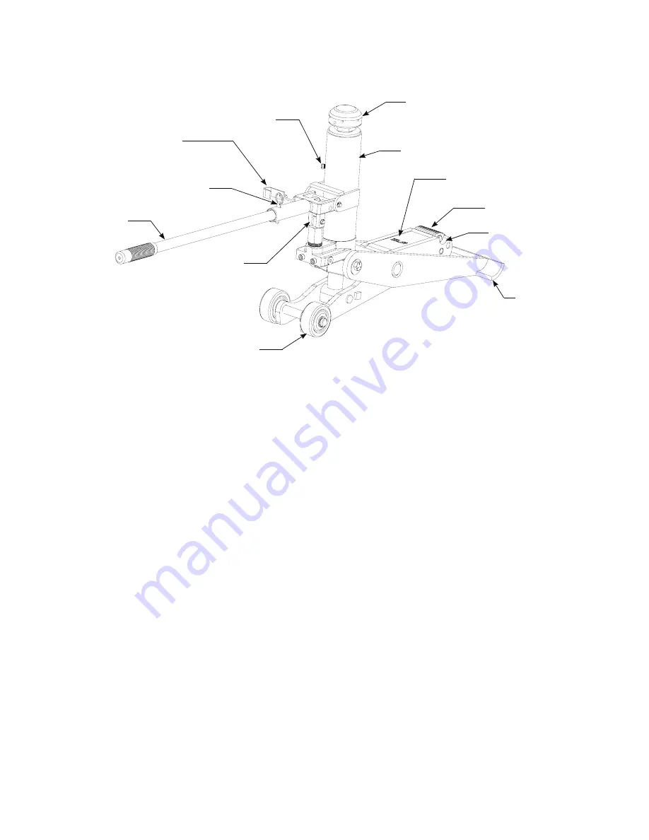
COMPONENT IDENTIFICATION

RELEASE KNOB

The release knob has a “Hold-to-Run

TM


” feature that utilizes a heavy-duty return spring to automatically close the 

release valve when the operator “lets go” of the release knob. With this feature, the operator should never have to 

physically close the valve by turning the release knob in a clockwise direction.

A mechanical stop prevents turning the release knob more than 1/2 turn counterclockwise.


WARNING! NEVER remove this mechanical stop. NEVER force the release knob more than 1/2 turn counter-clockwise 

as doing this may damage the release knob’s return spring.

If the valve ever behaves as it if is not completely closing (e.g., the jack won’t raise or won’t hold a load), the operator 

may gently turn the release knob in a clockwise direction until resistance is felt. The jack should then raise when the lift 

arm is pumped. If it does not, please call customer service for assistance.

Pump Handle

Serrated Lift Pad

Lift Arm

Front Foot Pad

Lift Arm Notch

Wheel

Quick Release-Locking Pin

J-Clip


(slips around pump plunger shaft to lock 

handle in UP position so jack can be dollied)

Pump Plunger 

Shaft

Fill Plug

Release Knob, Spring Loaded 

(Twist counter-clockwise and hold to 

lower jack)

Reservoir

Summary of Contents for SY8000

Page 1: ...nstructions Forklift Jack Operation Manual Note This manual contains important information about raising forklifts that you may not know Read this manual carefully and retain it for future reference U...

Page 2: ...ork Area 4 3 Select appropriate support strands and bring them to the immediate work area 6 4 Prepare the surrounding area before using the jack 7 5 Identify a lift point prepare the load for lifting...

Page 3: ...the forklift from the front or rear the wheels remaining on the ground must be chocked Use this jack only to raise forklifts This jack is not designed to raise loads other than forklifts Using this li...

Page 4: ...1 4 Starting Pad Height serrated lift pad 2 1 2 Weight 68 lbs Signal Words Signal words call attention to a safety message or messages or a property damage message or messages and designates a degree...

Page 5: ...ON RELEASE KNOB The release knob has a Hold to RunTM feature that utilizes a heavy duty return spring to automatically close the release valve when the operator lets go of the release knob With this f...

Page 6: ...wheeled to the work area if possible only lift and carry the jack if it cannot be wheeled safely Wheel the jack only across smooth surfaces If the surface is rough or uneven lift and carry the jack in...

Page 7: ...r as it will go and place the J clip around the p handle in the up position see gure 2 4 Push down on the pump handle to raise the front foot pad off the oor an wheels Quick Release Locking Pin Pump H...

Page 8: ...me lift point RNING NEVER use the pump handle to lift the jack The pump handle is not a properly balanced lev t for lifting the jack In addition a pump handle that is not properly pinned into the sock...

Page 9: ...times NEVER raise a 3 wheeled forklift from the 2 wheeled end or from the side NEVER use the jack to raise all four wheels of the forklift from the floor NEVER raise the forklift higher than 1 4 its...

Page 10: ...terweights see Figure 7B Figure 6 Figure 7A Figure 7B WARNING NEVER push the jack under the load past the red line marked on the decal located on top of the lift arm WARNING NEVER lift the forklift by...

Page 11: ...ccording to the forklift manufacturer s recommendations TVH provides support stands for this purpose Also read and follow all instructions and warnings provided with the support stands 2 Lower the for...

Page 12: ...it is cracked chipped rusted or shows signs of wear The jack should raise and lower smoothly through its full range Inspect the lift arm for damage such as bends and or twists Check the wheels to make...

Page 13: ...e following lubricants are requried Heavy grade machine oil Tellus T22 hydraulic oil or equivalent 3 Apply several drops of heavy grade machine oil to the pump plunger shaft and test the plunger for p...

Page 14: ...of this manual Release is open gently turn the release knob in a clockwise direction until resistance is felt See the Release Knob Hold To Run Feature section of this manual Overloaded use larger cap...

Page 15: ...t and roll pin 1 14 13 15 16 18 17 19 6 7 5 8 9 10 3 20 2 11 4 12 Soft Seal Kit 8 831 01002 Professional Service Equipment 3501 S Leonard Rd P O Box 728 St Joseph Missouri 64502 U S A Toll Free 800 82...

Page 16: ...D X 065 Thick 9 2 GR1 230 12001 Retaining Ring External 3 4 Diameter 10 2 GR1 831 04005 Actuator Turnnion Fitting 11 2 GR1 202 01403 Capscrew Hex Hd 1 2 20UNF St l Pltd Grade 5 Self Locking 1 1 2 Lg 1...

Page 17: ...15 Page 3 of 5 32 30 31 29 27 26 25 26 28 27 23 24 22 21 20 15 19 2 1 3 5 4 6 7 13 18 17 16 15 14 4 3 12 11 10 9 8...

Page 18: ...1 GR1 470 20003 Shaft Grooved Ends 3 8 Dia 35 1 GR2 232 20104 Pump Handle Drilled FLJ Page 4 of 5 DN040405 2005 Gray Automotive Products Co 670 90386 Rev C 35 33 27 34 35 34 33 32 31 30 29 28 27 26 2...

Page 19: ...rd FLJ 400C Page 5 of 5 DN040405 2005 Gray Automotive Products Co 670 90386 Rev C 7 1 2 4 3 6 5 8 Information Placard Warning FLJ 400B 670 10231 Information Placard Notice 670 10049 Information Placar...

Page 20: ...TVH Parts Co 16355 S Lone Elm Road Olathe KS 66062 Toll Free 800 255 4109 Fax 913 829 9208...

Reviews: