background image

8

9

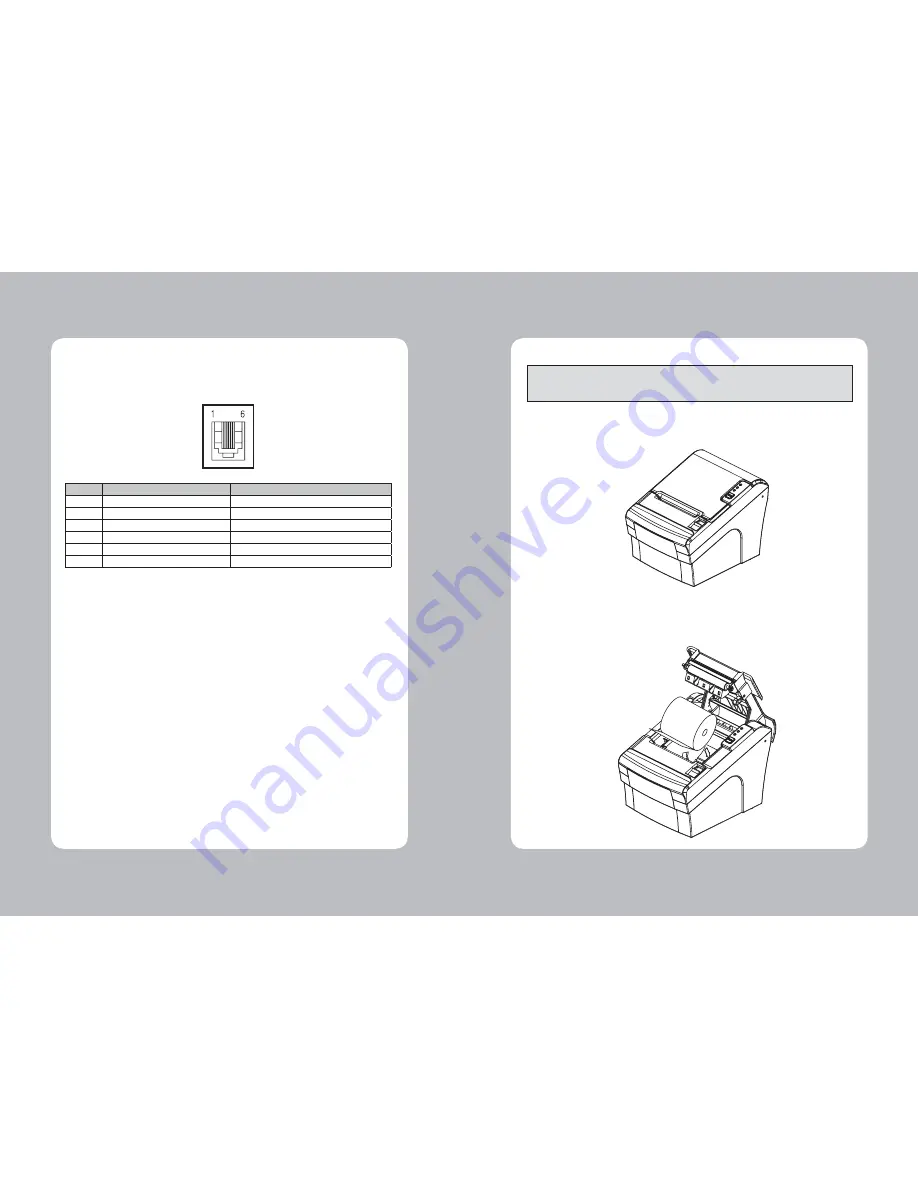
2-3. Loading the Roll Paper

Notes: Be sure to use paper rolls that meet the specifications. Do not use paper rolls that have the 
paper glued to the core because the printer cannot detect the paper end correctly. 
(Turn off power switch)

1. Make sure that the printer is not receiving data; Otherwise, data may be lost.

2. Open the paper roll cover by pushing down the cover open button.

3. Remove the used paper roll core if there is one inside.

4. Insert new paper roll as shown.

2-2-2. Cash Drawer Connector

The printer can operate two cash drawers with a 6 pin RJ-11 modular connector. 
The driver is capable of supplying a maximum current of 1.0A/24VDC for 510ms or less when not 
printing.

PIN

SIGNAL

DESCRIPTION

1

Signal GND

-

2

Drawer kick-out drive signal 1

Output

3

Drawer open/close signal

Input

4

+24V

-

5

Drawer kick-out drive signal 2

Output

6

Signal GND

-

Caution : To avoid an overcurrent, the resistance of the drawer kick-out solenoid must be 
               24

 Ω 

or more.

Summary of Contents for TP3000

Page 1: ...All specifications are subject to change without notice Receipt Printer User s Manual MODEL TP3000 ...

Page 2: ......

Page 3: ... 3 2 Error Indicating 14 4 Self Test 15 5 Hexadecimal Dump 16 6 Specifications 17 6 1 General Specifications 17 6 2 Auto Cutter Specifications 19 6 3 Interface 19 6 4 Electrical Characteristics 19 6 5 Environmental Requirements 20 6 6 Reliability 20 6 7 Certification 20 7 Command List 21 Table of Contents 1 Parts Identifications INTERFACE CONNECTOR PERIPHERAL DRIVE CONNECTOR POWER CONNECTOR INTERF...

Page 4: ...nclude these items If any items are damaged or missing please contact your dealer for assistance The Printer User s Manual Roll Paper Interface Cable optional Adaptor option 2 Setting Up the Printer INTERFACE CONNECTOR PERIPHERAL DRIVE CONNECTOR POWER CONNECTOR INTERFACE CONNECTOR USB For connection to a host computer For connection to a host computer For connection of the AC adapter Never unplug ...

Page 5: ...nput Printer select signal Ethernet Interface PIN SIGNAL I O 1 Data Out Output Data 2 Data Out Output Data 3 GND Ground 4 Data IN Input Data 5 Data IN Input Data 6 N C 7 N C 8 N C This equipment is indoor use and all the communication wirings are limited to inside of the building 2 2 1 Interface Connector D SUB 25 Female Serial Centronics Parallel USB A Type Ethernet Serial Interface PIN SIGNAL I ...

Page 6: ...button 3 Remove the used paper roll core if there is one inside 4 Insert new paper roll as shown 2 2 2 Cash Drawer Connector The printer can operate two cash drawers with a 6 pin RJ 11 modular connector The driver is capable of supplying a maximum current of 1 0A 24VDC for 510ms or less when not printing PIN SIGNAL DESCRIPTION 1 Signal GND 2 Drawer kick out drive signal 1 Output 3 Drawer open clos...

Page 7: ...n the cover of Dip Switch and change setting 2 4 1 Serial Interface Specification DIP Switch Setting Standard SW FUNCTION ON OFF 2 Hexadecimal HEXDUMP NORMAL 5 Cut Mode Full Cut Partial Cut 6 Handshaking XON XOFF DTR DSR 8 Paper Low Mode Paper Low Detect Do not detect Print Density Function SW 3 SW 4 Low Power ON ON Normal OFF ON Normal ON OFF Dark OFF OFF Baud rate selection Transmission Speed SW...

Page 8: ...Replace the DIP switch cover Then secure it with the screw The new settings take effect when you turn on the printer CAUTION When the paper is jammed with cutter the top cover might be stuck In this case repeat power on and off several times If the top cover is still stuck please follow the steps to release the papers from jamming 1 Make sure the printer is turned off 2 Remove the screw from the D...

Page 9: ...aper near end ON OFF ON Paper is low Test mode OFF OFF ON Ignored error led 3 Control panel and other functions The self test lets you know if your printer is operating properly It checks the control circuits printer mechanisms print quality ROM version and DIP switch settings This test is independent of any other equipment or software Running the self test 1 Make sure the printer is turned off an...

Page 10: ...tains the hexadecimal codes and the second column gives the ASCⅡ characters that correspond to the codes Hexadecimal Dump 1B 21 00 1B 26 02 40 40 1B 25 01 1B 63 34 00 1B c4 41 42 43 44 45 46 47 48 ABCDEFGH A period is printed for each code that has no ASCⅡequivalent 3 Turn off the printer and make sure that Dip sw 1 2 off 4 Turn on the printer 5 Hexadecimal Dump 6 Specifications Appendix A Specifi...

Page 11: ...s 6 3 Interface RS232C Serial Interface Centronics Parallel Interface IEEE1284 USB Interface USB COMBO Interface Ethernet Interface 10Mbps Wi fi 802 11b 6 4 Electrical Characteristics 1 Input Voltage DC 24V 10 2 Current Consumption Operating Approx 1 5 A at ASC printing Peak Approx 10 A at print duty 100 For 10 seconds or less Stand by Approx 0 15 A 3 Power Connector ...

Page 12: ...ge mode 33 ESC Set relative print position 34 ESC a Select justification 35 ESC c 3 Select paper sensor s to output paper end signals 36 ESC c 4 Select paper sensor s to stop printing 37 ESC c 5 Enable disable panel buttons 38 ESC d Print and feed paper n lines 39 ESC p General pulse 7 Command List Important When connecting or disconnecting the power supply from the printer be sure that the follow...

Page 13: ...t cut mode and cut paper 54 GS W Set printing area width 55 GS Set relative vertical print position in page mode 56 GS a Enable disable Automatic Status Back ASB 57 GS f Select font for HRI characters 58 GS h Set bar code height 59 GS k Print bar code 60 GS r Transmit status 61 GS v 0 Print raster bit image 62 GS w Set bar code width Add 1 ESC i Full cut 2 ESC m Partial cut 3 FS Set print mode s f...

Reviews: