


nozzle and continue foaming.
Close the hose-to-applicator valves (H). Remove spray
•
foam applicator from the hose to applicator valves,
aiming the valve into a waste container. Carefully open
the “A” hose to applicator valve to determine if chemical
flow is present. Close the “A” hose to applicator valve.
Repeat for the “B” hose. If chemicals flow from both
hoses and all other steps have been followed, replace
spray foam applicator. If nothing is coming through the
hoses and the chemical tanks are not empty, replace the
hoses.
For additional assistance, contact your Convenience
Products Sales Representative or Convenience Products
Customer Service at (800) 325-6180.
NOTE:
If spraying is stopped for longer than 30 seconds,
foam in the nozzle will begin to cure and clog. System
performance will be compromised. Replace the used
nozzle with an unused nozzle. Higher temperatures speed
curing, while lower temperatures slow curing.
NOZZLE REPLACEMENT
To replace the used nozzle, engage the safety on the foam
applicator
(Photo 6)
.
Grasp the spray foam applicator in one hand and the used
nozzle in the other. Twist the nozzle and pull it off the
barrel.
Place an unused nozzle on the barrel of the spray foam
applicator by pushing and twisting the nozzle until firmly
locked into place. The Touch ’n Seal CPDS Series 2 is ready
for operation.
SYSTEM SHUT DOWN PROCEDURE
(For end of day)
Engage the safety on the spray foam applicator.
Clean any chemical from the front of the spray foam
applicator barrel by wiping with a clean rag
(Photo 6)
.
Reattach the used nozzle. This provides an airtight seal
during storage.
Turn off the following valves:
Two hose-to-applicator on/off valves (H) by moving the
•
valve handle perpendicular to the valve
(Photo 2)
.
Two yellow air pressurization intake valves (top yellow
•
valves) (L) by turning clockwise.
Turn the Pressure Supply On/Off switch (B) to the “Off”
position.
Turn off and unplug the air compressor (S). Wrap the
compressor cord around the electric cord retention hooks.
Ensuring that the retention gate and toolbox lid are secured,
carefully tilt the CPDS Series 2 onto its back to access the
bottom of the cylinders.
Close the tank-to-hose valves (G) on the bottom of the
chemical cylinders by moving the valve handle perpendicular
to the valve
(Photo 2)
. Close the valves on the bottom of the
cylinders turning the yellow handle clockwise.
Carefully lift the CPDS Series 2 upright.
Coil the spray foam applicator and chemical hose assembly
without draining or depressurizing. Place on the chemical
hose storage hooks (D).
CPDS SERIES 2 HEATER OPERATION
The CPDS Forced Air Heating Unit, when used in conjunction
with the CPDS Series 2 Cover, will warm cold CPDS Series
2, a set of installed chemical cylinders and chemical hoses
up to and maintain appropriate operating temperatures
of 70°-90°F (21°-32°C). The length of time to raise the
temperature of the CPDS Series 2, chemical cylinders and
chemical hoses is dependent upon the recent storage and
ambient temperatures.
Stage the CPDS Series 2 with a set of installed
1.
chemicals and chemical hoses in the work area.
Cover the CPDS Series 2 with the CPDS Series 2 Cover
2.
(item # 4505500105). (See Photo Below)
Turn on the CPDS Forced Air Heating Unit. A simple on/
3.
off switch operates the CPDS Forced Air Heating Unit.
The CPDS Series 2 Forced Air Heating Unit has a built
in thermostat control that will cycle the unit off and
on as necessary. Use the thermostat control setting
to reach and maintain proper “system” temperatures.
Always use the “Thermostat Control” setting. (See
Photo Below)
Prep the work site.
4.
Turn off the CPDS Forced Air Heating Unit when the
5.
CPDS Series 2 System reaches the proper operating
temperature of 70°-90°F (21°-32°C) and you are
ready for spray application. Heat from the operating air
compressor will maintain the temperature of the CPDS
Series 2 and chemical cylinders during the spraying
operation as long as the CPDS Cover remains installed.
Do not operate in excess of 100°F under cover. Use the
CPDS Forced Air Heating Unit to keep the CPDS Series
2 System warm overnight (in a garage or warehouse)
or immediately prior to spraying operations. Keep CPDS
Series 2 chemical cylinders at recommended operating
temperatures to supply proper foam. The CPDS Cover
will protect the unit as well as help maintain proper
chemical temperatures when transporting to a job
site. Insulate chemical hoses from cold ambient and
surface temperatures to avoid affecting the quality of
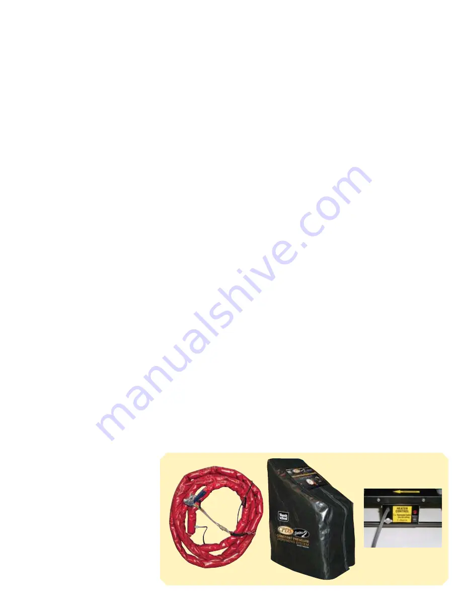
the foam. Use the CPDS Hose Warming Wrap (item #
4505500100) to ensure cold weather protection of
chemical hoses. (See Photo Below)
COLD WEATHER STARTING
Follow the steps below to ensure proper operation of the
compressor in cold conditions (below 50˚F (10˚C). Begin
spray foam application if compression starts after any of
these steps.
Keep the CPDS Series 2 warm (70˚F/21˚C-90˚F/30˚C)
1.
until immediately prior to use. This can be accomplished
by keeping the CPDS Series 2, chemical hoses and
chemical cylinders in a warm room.
Ensure that the compressor On/Off switch is in the
2.
“On” position and the compressor reset switch is
depressed (P).
Verify that all 3-prong electrical cords are properly
3.
connected and plugged into a “hot” 120V, 15 amp
receptacle.
Verify that the minimum gauge recommendations for
4.
grounded, 3-prong extension cords are followed:
a. 50’ or less in length: 12 gauge
b. up to 100’: 10 gauge
Ensure no other electrical appliances or tools are being
5.
used on the same circuit.
Turn the compressor On/Off switch to “Off”. Slowly
6.
loosen the air compressor water drain to relieve air
pressure (about 1/2 turn). Once the air pressure has
been relieved, turn the compressor On/Off switch to
“On”, allow to run for 5-10 seconds and hand tighten
the water drain valve.
If none of the above steps solve the problem, call your local
Convenience Products Sales Representative or Convenience
Products Customer Service at (800) 325-6180.
REPLACING EMPTY CYLINDERS
NOTE:
Chemical cylinders should empty at approximately
the same time. A small amount of chemical may be left in
one or both cylinders.
Engage the spray applicator safety.
Position the CPDS Series 2 on a level surface and lock the
front casters to prevent accidental movement.
Close the following valves:
Two yellow air pressurization intake valves (L) by turning
•
clockwise.
Two
•
hose-to-applicator on/off valves (H).
Turn the Pressure Supply On/Off switch to the “Off”
position.
Turn off and unplug the air compressor. Wrap the com-
pressor cord around the electric cord retention hooks.
remove both air hose-to-cylinder air pressure hoses (M),
slowly releasing any existing air pressure.
Ensuring that the retention gate and the toolbox lid are
secured, carefully tilt the CPDS Series 2 back to access the
bottom of the cylinders.
Close the tank-to-hose on/off valves (G) on the bottom
of the chemical cylinders by moving the valve handle
perpendicular to the valve. Close the valves on the bottom
of the cylinders turning the yellow handle clockwise.
Unhook the chemical hoses from the strain relief fixture (T).
Holding a rag under the valve connection point, slowly
remove each of the tank-to-hose on/off valves (G) from
the bottom of the chemical cylinders.
Do not remove the
hose-to-applicator valves (H) from the chemical hoses.
A small amount of chemical will drip from the cylinder
chemical valves and the chemical hose valves. Remove all
residue and clean all fittings with a rag and Touch ‘n Seal
Poly-Clean. Be sure to wear personal protective equipment.
Keep the exposed ends of the valves clean.
Carefully lift the CPDS Series 2 back into the upright
position. Remove the retention gate and remove each
empty cylinder. Install new chemical cylinders as per
previous instructions in “INSTALLATION & SET UP”.
Hose Warming Wrap
CPDS Cover
Forced Air Heating Unit


