background image

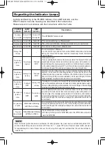
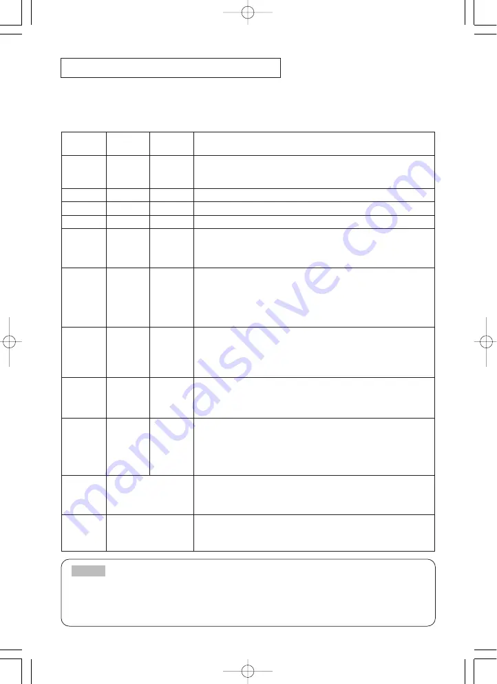
Regarding the Indicator Lamps

Lighting and flashing of the POWER indicator, the LAMP indicator, and the
TEMP indicator have the meanings as described in the Table below.
Please respond in accordance with the instructions within the Table.

POWER

indicator

LAMP

indicator

TEMP

indicator

Description

The orange

lamp is lighted

Turned OFF

(Not lighted)

Turned OFF

(Not lighted)

The STANDBY mode is set

Flashing of the green lamp

Turned OFF

Turned OFF

The unit is warming up. Please wait.

The green lamp is lighted

Turned OFF

Turned OFF

The unit is in an ON state. Ordinary operations may be performed.

Flashing of the orange lamp

Turned OFF

Turned OFF

The unit is cooling down. Please wait.

Blinking of the

red lamp

-

-

The unit is cooling down. Please wait.
A certain error has been detected. Wait until the POWER indicator lamp has finished
flashing, and then perform the proper response measure using the item descriptions
below as reference.

The red lamp

is lighted, or

blinks

The red lamp

is lighted

Turned

OFF

The lamp does not light.
There is a possibility that the interior portion has become heated. Turn the power OFF and wait
approximately 20 minutes. After the main unit has cooled down, please confirm whether or not
there is blockage of the air passage aperture, whether or not the filter is dirty, and/or whether or
not the peripheral temperature exceeds 35°C, etc. After performing any needed maintenance,
turn the power ON again; if the same display is displayed, then please change the lamp.

The red lamp

is lighted, or

blinks

Blinking of the

red lamp

Turned

OFF

Either there is no lamp and/or lamp cover, or either of these has not been properly fixed
(attached). Turn the power OFF and wait approximately 45 minutes. After the main unit has
sufficiently cooled down, please make confirmation of the attachment state of the lamp and
lamp cover. After performing any needed maintenance, turn the power ON again; if the same
display is displayed, then please contact a sales store or a service company.

The red lamp

is lighted, or

blinks

Turned

OFF

Blinking of the

red lamp

The cooling fan is not operating. Turn the power OFF and wait approximately 20 minutes. After the
main unit has cooled down, please make confirmation that no foreign matter has become caught in
the fan, etc. After performing any needed maintenance, turn the power ON again; if the same display
is displayed, then please contact a sales store or a service company.

The red lamp is

lighted, or

blinks

Turned

OFF

The red lamp is

lighted

There is a possibility that the interior portion has become heated. Turn the power OFF and wait
approximately 20 minutes. After the main unit has cooled down, please confirm whether or not
there is blockage of the air passage aperture, whether or not the filter is dirty, and/or whether or
not the peripheral temperature exceeds 35°C, etc. After performing any needed maintenance,
turn the power ON again; if the same display is displayed, then please contact a sales store or a
service company.

The green lamp

is lighted

Alternative blinking

with the red lamp

There is a possibility that the interior portion has become overcooled. Please use the unit within
the usage temperature parameters (0°C to 35°C). After performing any needed maintenance,
turn the power ON again; if the same display is displayed, then please contact a sales store or a
service company.

The green

lamp is lighted

Simultaneous blinking

with the red lamp

This is a notification that it is time to clean the filter.
After cleaning the filter, operate the FILTER TIME portion of the OPTION Menu, and perform
reset of the FILTER TIME.

When the interior portion has become overheated, for safety purposes, the power source is automatically turned OFF,
and the indicator lamps may also be turned OFF. Press the “

” (power OFF) side of the main power switch, and wait

for approximately 20 minutes. Please then use the unit only after having first confirmed that the unit has sufficiently

cooled down.

NOTE

8

ED-S3170/X3270/Vol.2/ENG    03.8.29  3:36  PM    ページ 8

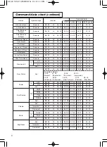
Summary of Contents for ED-S3170AT

Page 1: ...rks of the Video Electronics Standard Association Windows is a registered trademark of Microsoft Corporation All other trademarks are the property of their respective owners NOTE WARNING Please read t...

Page 2: ...d Perform each operation in accordance with the instructions in the Table Menu screen display Press the MENU button Menu selection Choose a menu name using the button and press the button or the ENTER...

Page 3: ...Vertical Position for RGB Up Down H POSITION Adjust Horizontal Position for RGB Left Right H PHASE Adjust Horizontal Phase for RGB Right Left Adjust to eliminate flicker H SIZE Adjust Horizontal Size...

Page 4: ...ation requires approximately 10 seconds VIDEO Select Mode of Signal Type for VIDEO S VIDEO AUTO NTSC PAL SECAM NTSC4 43 M PAL N PAL Selecting AUTO mode activates and performs the AUTO function for VID...

Page 5: ...the MyScreen or ORIGINAL screen it will turn immediately to a solid black screen MyScreen Registration of MyScreen When this item is executed the MyScreen Menu for registration of MyScreen for the BLA...

Page 6: ...is being displayed The reset menu will then appear After you replace the lamp with a new lamp select RESET on the menu with the button Do not reset the lamp time unless you have replaced the lamp And...

Page 7: ...is recommended Note 2 When lamp usage reaches 2 000 hours the power will automatically be turned OFF Please change the lamp by referring to THE LAMP in Vol 1 Basic After you have changed the lamp ple...

Page 8: ...again if the same display is displayed then please contact a sales store or a service company The red lamp is lighted or blinks Turned OFF Blinking of the red lamp The cooling fan is not operating Tur...

Page 9: ...al wiring to this unit is not correctly connected Correctly connect the connection cord Vol 1 10 11 The volume setting has been set at or adjusted to an extremely low level Adjust the VOLUME setting t...

Page 10: ...0W Power supply AC100 120V 2 7A AC220 240V 1 3A Power consumption 240W Temperature range 0 35 C Operating Size 295 W x 87 5 H x237 D mm Weight mass 2 7 kg Ports Optional Parts RGB Ports RGB IN 1 2 2 V...

Page 11: ...THINK A MACHINE DEFECT HAS OCCURRED section and run through the suggested checks If this does not resolve the problem contact your dealer or service company They will tell you what warranty condition...

Page 12: ...Vp p 75 terminator RCA jack S VIDEO IN Brightness signal 1 0Vp p 75 terminator Color signal 0 286Vp p NTSC burst signal 75 terminator 0 300Vp p PAL SECAM burst signal 75 terminator Mini DIN 4 pin jack...

Page 13: ...0 VESA SXGA 60Hz Zoom out Zoom out 1280 1024 64 0 60 0 VESA SXGA 60Hz Zoom out Zoom out 1280 1024 80 0 75 0 VESA SXGA 75Hz Zoom out Zoom out 1280 1024 91 2 85 0 VESA SXGA 85Hz Zoom out Zoom out 1600 1...

Page 14: ...A 60Hz 2 1 2 5 15 8 0 4 XGA 70Hz 1 8 1 9 13 7 0 3 XGA 75Hz 1 2 2 2 13 0 0 2 XGA 85Hz 1 0 2 2 10 8 0 5 1152 864 75Hz 1 2 2 4 10 7 0 6 1280 960 60Hz 1 0 2 9 11 9 0 9 1280 1024 60Hz 1 0 2 3 11 9 0 4 1280...

Page 15: ...b 15 pin shrink jack Serial Mouse 2 1 4 3 6 5 2 1 4 3 6 5 8 7 10 9 8 7 9 12 11 14 13 15 RI CD RD TD DTR GND DSR CTS RTS RTS GND SEL0 TD 2 1 4 3 6 5 8 9 7 Mouse jack D sub 9 pin Projector Computer 1 2...

Page 16: ...ing 19200bps 8N1 1 Protocol Consist of header 7 bytes command data 6 bytes 2 Header BE EF 03 06 00 CRC_low CRC_high CRC_low Lower byte of CRC flag for command data CRC_high Upper byte of CRC flag for...

Page 17: ...1 The computer sends the decrement code Header Command data 05H 00H type 2 bytes 00H 00H to the projector 2 The projector decreases the setting value on the above setting code 3 The projector returns...

Page 18: ...00 Get BE EF 03 06 00 38 D2 02 00 04 30 00 00 Language Set English BE EF 03 06 00 F7 D3 01 00 05 30 00 00 Fran ais BE EF 03 06 00 67 D2 01 00 05 30 01 00 Deutsch BE EF 03 06 00 97 D2 01 00 05 30 02 00...

Page 19: ...0 30 01 00 Get BE EF 03 06 00 C8 D8 02 00 20 30 00 00 Error Status Get BE EF 03 06 00 D9 D8 02 00 20 60 00 00 Example of Return 00 00 01 00 02 00 03 00 Normal Cover error Fan error Lamp error 04 00 05...

Page 20: ...BE EF 03 06 00 AD D0 02 00 08 20 00 00 Picture Position at 16 9 or Small Set Default BE EF 03 06 00 62 D1 01 00 09 20 00 00 Bottom BE EF 03 06 00 F2 D0 01 00 09 20 01 00 Top BE EF 03 06 00 02 D0 01 00...

Page 21: ...R Set NORMAL BE EF 03 06 00 3B 23 01 00 00 33 00 00 WHISPER BE EF 03 06 00 AB 22 01 00 00 33 01 00 Get BE EF 03 06 00 08 23 02 00 00 33 00 00 GAMMA Set NORMAL BE EF 03 06 00 C7 F0 01 00 A1 30 00 00 CI...

Reviews: