background image

9

ASSEMBL

Y

/MOUNTING

Figure D

 MM493B

Do not use the machine until it is completely 

assembled and you have read and understood 

the entire operating manual.

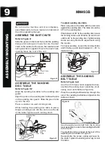
ASSEMBLE THE DUST CHUTE

Refer to Figure D

Slide the groove in the dust chute onto the sanding 

disc guard casting as shown. Secure the dust 

chute to the sander with screws, flat washers and

spring washers supplied. Ensure the dust chute

opening faces the rear of the unit.

Dust Chute

Screws

Flat 

Washers

Washers

Groove

Sanding Disc

ASSEMBLE THE SANDING

DISC TABLE

Refer to Figure E,F

Align the sanding disc table to the sanding disc

guard.
Align the pins on the sanding disc table with slots 

on the sanding disc guard. Slide the pins in and 

up into the slot.
Place a washer on each locking knob.
While holding the sanding disc table in place, 

thread a locking knob into the slot on each side 

of the table.Tighten each locking knob.

Sanding Disc 

Guard

Slot

Hole for 

Locking 

Knob 

Locking 

Knob and 

Washer

Sanding 

Disc 

Table

Pins

Figure E

To adjust sanding disc table

Place a square on the table with the ruler side

against the sanding disc. The table should be 

90° to the sanding disc.
If the table is not 90° to the sanding disc, loosen 

the locking knobs and tilt table up and down 

until it is 90° to the sanding disc. Tighten locking 

knobs securely.Recheck adjustment using

the square.
For bevel sanding, loosen the locking knobs 

and tilt table up and down between 0 – 45° to 

desired angle.

Sanding 
Disc Table

Locking 

Knob

Figure F

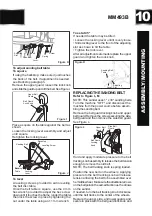
ASSEMBLE THE SANDING

BELT TABLE

Refer to Figure G–K

Use the 4 mm hex wrench supplied to disa-

ssemble the locking lever assembly. (bolt,

spring, lever and shaft,see Figure G).
Pass the sanding belt/backstop through the 

slot of the sanding belt table and position the

table as shown.

Use the washer and shaft from the locking 

lever assembly to secure the sanding belt table 

to the frame.
The shaft should be placed at the rear of the 

adjusting slot as shown in Figure H
Reassemble the screw, spring and lever to 

the shaft. Tighten the locking lever fully to lock 

the table.

Figure G

Sanding 

Belt

Sanding Belt Table

Slot

Summary of Contents for MM493B

Page 1: ...1 X 30 BELT AND 5 DISC SANDER INSTRUCTION MANUAL IMPORTANT For your own safety read and follow all of the Safety Guidelines and Operating Instructions before operating this product MM493B...

Page 2: ...LY MOUNTING 12 OPERATION 13 MAINTENANCE 14 TROUBLESHOOTING GUIDE 16 EXPLONED VIEW 17 PARTS LIST 19 WARRANTY 20 ELECTRICAL SAFETY 6 SPECIFICATIONS 2 Motor 120VAC 60Hz 2 3Amp 1 3HP Phase Single Disc Spe...

Page 3: ...think clearly Never operate power tools when tired intoxicated or when taking medications that cause drowsiness WORK AREA PREPARATION Keep work area clean Cluttered work areas invite accidents Do not...

Page 4: ...ury could occur if tool is tipped or if belt or disc are unintenti onally contacted Know your tool Learn the tool s operation application and specific limitations Use recommended accessories refer to...

Page 5: ...ing Prong 3 Prong Plug Figure A Do not permit fingers to touch the terminals of plug when installing or removing from outlet Plug must be plugged into matching outlet that is properly installed and gr...

Page 6: ...r Continuous Duty 1 3 Voltage 120 Amp 2 3 Hertz 60 Phase Single RPM 3450 ELECTRICAL CONNECTIONS off and disconnected from power source while motor is mounted connected reconnected or anytime wiring is...

Page 7: ...der Assembly with Abrasive Belt and Disc Sanding Disc Table Miter Gauge Sanding Belt Table Dust Chute with dust nozzle adapter Locking Knobs sanding disc table Washers sanding disc table Washer 8 mm S...

Page 8: ...8 KEY PARTS DIAGRAN Sanding Belt Locking Lever Switch Enclosed Induction Motor Dust Chute Cast AL Base MM493B Sanding Belt Table Sanding Disc Sanding Disc Table...

Page 9: ...and Washer Sanding Disc Table Pins Figure E To adjust sanding disc table Place a square on the table with the ruler side against the sanding disc The table should be 90 to the sanding disc If the tabl...

Page 10: ...adjusting slot as shown to tilt the table Tighten the lock lever After all adjustments are made replace the upper guard and tighten the lock knob Sanding Belt Table Lever Adjusting Slot Figure K REPL...

Page 11: ...d locking knob and upper belt guard Remove the screws securing the side belt guard and then remove the side belt guard See Figure L Rotate the sanding belt by hand to check the belt tracking The belt...

Page 12: ...lection system is strongly recommended when using the belt disc sander Use of a mask or respirator is still recommended even when using a dust collection system Dust Port Adapter Dust Port Adapter Dus...

Page 13: ...wise downward toward the work table on the left side of the sanding disc and upward from the work table CAUTION on the right side of the sanding disc Always use the left side of the sanding disc using...

Page 14: ...e permanently lubricated at the factory They require no further lubrication When operation seems stiff a light coat of paste wax applied to the table will make it easier to feed the work while finishi...

Page 15: ...ry MM493B Sanding surface clogs quickly 1 Too much pressure against belt disc 2 Sanding softwood 1 Reduce pressure on workpiece while sanding 2 Use different stock different sanding accessories or acc...

Page 16: ...r breaker 4 Reduce the load on the motor Motor overheats 1 Motor overloaded 2 Extension cord too long and of insufficient gauge weight 1 Reduce load on motor pressure on object being sanded 2 Utilize...

Page 17: ...BD4603 17 MM493B EXPLODED VIEW...

Page 18: ...M6 Belt Guard Plate Rotor Phillips Screw M4x8 Sanding Belt Platen Flat Washer D4 Hex Nut M4x10 Cover Locking Knob Sanding Belt Safeguard Sanding Belt Bracket Cover Sanding Belt 1 x30 100 Grit Idler W...

Page 19: ...uard Adjusting Spring Locking Nut M10 Adjusting Fixing Board Adjusting Spring Adjusting Knob Phillips Screw ST4 2x16 Spring Column Pin 3x20 Adjusting Shaft Adjusting Spring Large Flat Washer D5 C Clip...

Page 20: ...Having Problems Give us a chance to help you before returning this product Email After the phone 844 866 5687 ONE YEAR LIMITED WARRANTY PARTS LIST 20 MM493B WARRANTY info toolots com...

Reviews: