


14
TLGS625
MAINTEN
ANCE
Before mounting a new grinding wheel, it must
be inspected. DO NOT assume that a wheel
is in sound condition because it is new. Dam-
age can occur during shipping, with age or
exposure to moisture.
Visually inspect the wheel. Look for any cr-
acks, chips, nicks or dents in the wheel’s
surface. DO NOT use the wheel if you see any
of these, Perform a Ring Test. This test will
give you an indication of any internal damage
that may not be obvious during a visual inspection.
To perform a Ring Test:
1. Make sure the wheel that you test is clean
and dry; otherwise, you may get false results.
2. Balance the wheel with your finger in the
hole if size permits, If this is not possible,
hang the wheel in the air with a piece of
cord or string looped through the hole in
the centert.
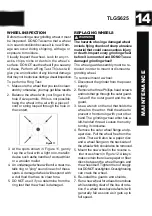
WHEEL INSPECTION
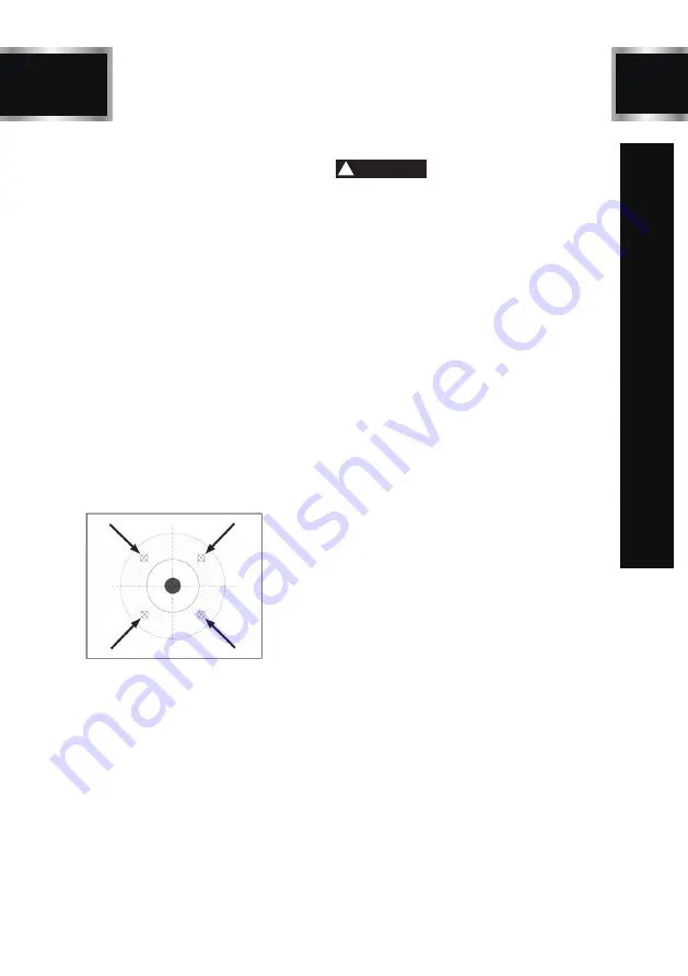
3. At the spots shown in Figure 11, gently
tap the wheel with a light non-metallic
device such asthe handle of a screwdriver
or a wooden mallet.
4. An undamaged wheel will emit a clear me-
tallic ring or "ping" sound in each of these
spots. A damaged wheel will respond with
a dull thud that has no clear tone.
5. DO NOT use it if you determine from the
ring test that the wheel is damaged.
Figure 11
REPLACING WHEELS
The wheel guard assembly must be re-
moved in order to mount or dismount a
grinding wheel.
To remove/mount a wheel:
1. Disconnect the grinder from the power
supply.
2. Remove the three Phillips head screws
and nuts that go through the outer guard.
Take off the outer guard and the rim
guard.
3. Use a wrench on the nut that holds the
wheel on the arbor. Hold the wheel to
prevent it fromturning with your other
hand. The grinding wheel arbor has a
left-handed thread. Loosen the nut by
turning it clockwise.
4. Remove the outer wheel flange and p-
aper disc. Pull the wheel free from the
arbor. There will also be a paper disc
and a wheel flange on the back side of
the wheel which should also be removed.
5. Mount the new wheel in the reverse o-
rder or as shown in Figure 12. Always
make certain there is are paper or fiber
discs between the wheel flanges and
the wheel itself. Tighten the nut snugly
but DO NOT over-tighten. Over-tightening
can crack the wheel.
6. Re-install the guards and shields.
7. Run a new wheel for at least one minute
while standing clear of the line of rota-
tion. If a wheel does have defects it will
generally fail as soon as it gets up to
full speed.
The hazards of using a damaged wheel
include flying chunks of sharp abrasive
material that could cause serious injury
or death. Inspect every grinding wheel
before it is mounted and DO NOT use a
damaged grinding wheel!
WARNING
!
Summary of Contents for TLGS625
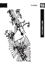
Page 18: ...18 EXPLONED VIEW TLGS625...


