background image

13

14

4. ACCURACY CHECK

This instrument requires no calibration. The regular accuracy checks ensure that the 

instrument’s accuracy has not been impaired by falls or heavy impacts. 

It is recommended to check the laser level accuracy each time before beginning workday 

usage. The accuracy check procedure includes three steps: the horizontal line height check 

(step 1)

, the horizontal line leveling check 

(step 2)

, the vertical line leveling check 

(step 3)

.

If, during one of the tests, the measured deviation exceeds the allowable deviation, repeat 

the test procedure. Should the readings persist over the allowable deviation, the instrument 

is out of calibration and must be serviced.

Contact ToughBuilt

®

 Customer Service for additional support.

The following accuracy check procedure suggests the most practical scenarios  

at the recommended distance.

The surface of the area where the accuracy check procedure is conducted must be 

sufficiently level, so that the instrument remains within the self-leveling range of ± 4°  

from the 0° level position. 


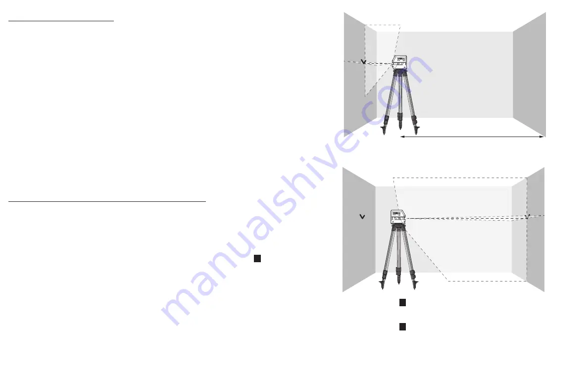
Step 1:

 Checking the Height Accuracy of the Horizontal Line

For this check, a minimum measuring distance of 16' (5m) from the instrument to the 

opposite wall in a dimly lit room is required.

1.

  Place the instrument on a firm and level surface or mount the instrument onto a tripod 

close to 

wall A.

2.

  Turn on the instrument in the self-leveling mode by sliding the Pendulum Switch 

 2 


to the UNLOCK position.

3.

  Direct the laser beam against wall A and allow a few seconds for the visible line to 

stabilize. Mark the center of the horizontal line projected by the instrument on 

wall A (point a1). 


4.

  Rotate the instrument by 180°, allow it to self-level, and mark the center of the horizontal 

line on the opposite 

wall B (point b)

.

5.

  Slide the Pendulum Switch 

 2 

 to the LOCK position.

6.

  Without turning the instrument, place it close to 

wall B.

7.

  Slide the Pendulum Switch 

 2 

 to the UNLOCK position and allow the visible line  

to stabilize. 

B

A

a1

16'  (5m)

B

A

a1

b

Summary of Contents for TB-H2-LL-100-L2

Page 1: ...2 OPERATING SAFETY INSTRUCTIONS IMPORTANT Read all safety warnings and instructions before using ToughBuilt Industries Inc 6671 S Las Vegas Blvd Building D Suite 210 Las Vegas NV 89119 USA Made in Chi...

Page 2: ...g Function 9 QuickSet Rotating Mount and Ceiling Bracket 9 Using QuickSet Rotating Mount 10 Using Ceiling Bracket 12 Working with the Laser Target Plate 12 4 ACCURACY CHECK 13 5 TROUBLESHOOTING 20 6 C...

Page 3: ...isassemble or modify the device Tampering with this device may result in hazardous laser radiation exposure and will automatically void all warranties DO NOT leave the device turned on when unattended...

Page 4: ...NOT mix battery chemistries DO NOT short battery terminal ALWAYS check battery posts in the battery compartment for corrosion Clean the posts before use DO NOT use batteries with corroded terminals D...

Page 5: ...oss Lines Working Range Up to 100 30 5m Laser Beam Color Green Laser Type Emission Wave Length of 510 530 nm Class 2 1 mW Accuracy 1 8 33 3 18mm 10 1m Self Leveling Range 4 degrees Operating Temperatu...

Page 6: ...t first DO NOT turn on a wet or damp instrument To wipe the Laser Beam Window 1 use ONLY a lint free cloth DO NOT USE A PAPER TOWEL PLEASE NOTE Laser beam expands as the distance between the instrumen...

Page 7: ...selected both in the Self Levelling Mode and in the Pendulum Locked Mode QuickSet Rotating Mount and Ceiling Bracket The QuickSet Rotating Mount and Ceiling Bracket allow mounting the laser instrumen...

Page 8: ...een the magnetic surfaces Working with the Laser Target Plate The Laser Target Plate 14 improves the visibility of the laser beam under unfavorable light conditions and at long distances within the wo...

Page 9: ...k procedure is conducted must be sufficiently level so that the instrument remains within the self leveling range of 4 from the 0 level position Step 1 Checking the Height Accuracy of the Horizontal L...

Page 10: ...responding Distance Between Walls in the table below the instrument must be serviced Step 2 Checking the Leveling Accuracy of the Horizontal Line For this check a 16 5m or 30 9m distance to the opposi...

Page 11: ...f the door opening point a at an 8 2 5m distance beyond the other side of the door opening point b and at the upper edge of the door opening point c1 4 Swivel the instrument 45 to the right to positio...

Page 12: ...Cannot Power OFF Pendulum Switch 2 is in the UNLOCK position Slide the Pendulum Switch 2 to the LOCK position then press the Power ON OFF button 5 Out of Level Laser Beam Laser Beam out of leveling ca...

Page 13: ...sed of with household waste Please sort it out for separate recycling Separate collection of used products and packaging allows materials to be recycled and used again Reuse of recycled materials help...

Page 14: ...23 24...

Reviews: