background image


User Manual for Machine Vision Cameras 


Summary of Contents for I3CMOS00500KMA

Page 1: ...1 User Manual for Machine Vision Cameras...

Page 2: ...RS 9 7 1 8 I3CMOS series camera specifications Monochromatic GS or RS 9 8 2 SWIR series camera specification 9 2 1 Application of SWIR camera 9 2 2 SWIR1300KMA Specification 10 2 3 SWIR330KMA Specifi...

Page 3: ...MA 50 5 2 IUC26000KPA 51 5 3 IUC31000KMA 52 5 4 IUC31000KPA 53 5 5 IUC60000KMA 54 5 6 IUC60000KPA 55 6 I3ISPM series technical specifications 56 6 1 I3ISPM00500KPA 56 6 2 I3ISPM01500KPA 57 6 3 I3ISPM0...

Page 4: ...king information 80 8 5 I3CMOS and I3ISPM series camera dimensions and outputs 81 8 5 1 I3CMOS and I3ISPM series camera mechanical housing dimensions 81 8 5 2 I3CMOS and I3ISPM series camera interface...

Page 5: ...ent 105 11 8 5 Image flip 106 11 8 6 Test pattern 106 11 9 I3 series camera s I O electrical properties 108 11 9 1 I3 series camera s opto isolated input circuit line0 108 11 9 2 I3 series camera s op...

Page 6: ...camera which having built in hardware ISP to ensure color reproduction and higher video speed The resolution coverage is from 1 7MP to 43MP 1 2 Characteristics Sony Exmor back illuminated CMOS sensor...

Page 7: ...x2 4 760mv with 1 30s 0 15mv with 1 30s 59 9fps 3072 2048 59 9fps 1536 1024 1x1 2x2 17us 15s IUA6300KPA 6 3M IMX178LQJ C RS 1 1 8 7 37x4 92 2 4x2 4 425mv with 1 30s 0 15mv with 1 30s 59 8fps 3072 2048...

Page 8: ...0us 15s IUC31000KMA 31 0M IMX342LLA M GS 1 8 22 3x16 74 APS C 3 45x3 45 1830mv with 1 30s 0 15mv with 1 30s 12 0fps 6464 4852 45 9fps 3216 2426 1x1 2x2 31us 15s IUC31000KPA 31 0M IMX342LQA C GS 1 8 22...

Page 9: ...3 5 86x5 86 1650mv with 1 30s 0 15mv with 1 30s 164 5fps 1920 1200 1x1 15us 15s I3CMOS02300KMB IM702300B 2 3M IMX249LLJ M GS 1 1 2 11 25x7 03 5 86x5 86 1650mv with 1 30s 0 15mv with 1 30s 30fps 1920 1...

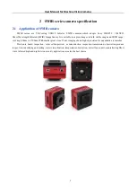
Page 10: ...es in both visible range and SWlR range covering 400nm to 1700nm With smaller pixel size of 5um imaging shows higher precision for quantitative researches Electronic board inspection solar cellinspect...

Page 11: ...e Full Well 181 6ke SNRmax 52 6dB Sensitivity 121mV Dark current 383e s 0C 510e s 10C 638e s 20C Gain range 1x 15x Exposure time 50 s 60sec Shutter Global shutter Binning Software2x2 3x3 4x4 Data inte...

Page 12: ...User Manual for Machine Vision Cameras 11 2 1 SWIR1300KMA spectral response curve 2 2 SWIR1300KMA relative quantum efficiency 2 3 SWIR1300KMA absolute quantum efficiency...

Page 13: ...211e Full Well 181 6ke SNRmax 52 6dB Sensitivity 121mV Dark current 383e s 0C 510e s 10C 638e s 20C Gain range 1x 15x Exposure time 50 s 60sec Shutter Global shutter Binning Software2x2 3x3 4x4 Data i...

Page 14: ...User Manual for Machine Vision Cameras 13 2 4 SWIR330KMA spectral response curve 2 5 SWIR330KMA relative quantum efficiency 2 6 SWIR330KMA absolute quantum efficiency...

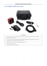
Page 15: ...5 2cm H 16 7cm TBD C One SWIR series camera C mount D D1 D2 D3 and D4 are national standard American Standard European standard and British standard power lines respectively E Power adapter input AC 1...

Page 16: ...lobal Shutter Binning Software2x2 3x3 4x4 Data interface USB3 0 USB3 1 GEN1 Digital I O One optical coupling isolated input one optical coupling isolated output two non isolated input and output Data...

Page 17: ...Software2x2 3x3 4x4 Data interface USB3 0 USB3 1 GEN1 Digital I O One optical coupling isolated input one optical coupling isolated output two non isolated input and output Data Format Mono8 Mono12 G...

Page 18: ...Software2x2 3x3 4x4 Data interface USB3 0 USB3 1 GEN1 Digital I O One optical coupling isolated input one optical coupling isolated output two non isolated input and output Data Format Mono8 Mono12 G...

Page 19: ...x2 Software 2x2 3x3 4x4 Data interface USB3 0 USB3 1 GEN1 Digital I O One optical coupling isolated input one optical coupling isolated output two non isolated input and output Data format RAW8 RAW12...

Page 20: ...are 2x2 3x3 4x4 Data interface USB3 0 USB3 1 GEN1 Digital I O One optical coupling isolated input one optical coupling isolated output two non isolated input and output Data format RAW8 RAW12 RGB8 RGB...

Page 21: ...Software2x2 3x3 4x4 Data interface USB3 0 USB3 1 GEN1 Digital I O One optical coupling isolated input one optical coupling isolated output two non isolated input and output Data Format Mono8 Mono12 Ge...

Page 22: ...4 Data interface USB3 0 USB3 1 GEN1 Digital I O One optical coupling isolated input one optical coupling isolated output two non isolated input and output Data Format RAW8 RAW12 RGB8 RGB24 RGB32 RGB48...

Page 23: ...ning Software 2x2 3x3 4x4 Data interface USB3 0 USB3 1 GEN1 Digital I O One optical coupling isolated input one optical coupling isolated output two non isolated input and output Data format Mono8 Mon...

Page 24: ...x3 4x4 Data interface USB3 0 USB3 1 GEN1 Digital I O One optical coupling isolated input one optical coupling isolated output two non isolated input and output Data format RAW8 RAW12 RGB8 RGB24 RGB32...

Page 25: ...ng Software 2x2 3x3 4x4 Data interface USB3 0 USB3 1 GEN1 Digital I O One optical coupling isolated input one optical coupling isolated output two non isolated input and output Data format Mono8 Mono1...

Page 26: ...4x4 Data interface USB3 0 USB3 1 GEN1 Digital I O One optical coupling isolated input one optical coupling isolated output two non isolated input and output Data format RAW8 RAW12 RGB8 RGB24 RGB32 RG...

Page 27: ...inning Software 2x2 3x3 4x4 Data interface USB3 0 USB3 1 GEN1 Digital I O One optical coupling isolated input one optical coupling isolated output two non isolated input and output Data format Mono8 M...

Page 28: ...inning Software 2x2 3x3 4x4 Data interface USB3 0 USB3 1 GEN1 Digital I O One optical coupling isolated input one optical coupling isolated output two non isolated input and output Data format Mono8 M...

Page 29: ...x2 Software 2x2 3x3 4x4 Data interface USB3 0 USB3 1 GEN1 Digital I O One optical coupling isolated input one optical coupling isolated output two non isolated input and output Data format RAW8 RAW12...

Page 30: ...re 2x2 3x3 4x4 Data interface USB3 0 USB3 1 GEN1 Digital I O One optical coupling isolated input one optical coupling isolated output two non isolated input and output Data format RAW8 RAW12 RGB8 RGB2...

Page 31: ...ware 2x2 Software 2x2 3x3 4x4 Data interface USB3 0 USB3 1 GEN1 Digital I O One optical coupling isolated input one optical coupling isolated output two non isolated input and output Data format Mono8...

Page 32: ...2 Software 2x2 3x3 4x4 Data interface USB3 0 USB3 1 GEN1 Digital I O One optical coupling isolated input one optical coupling isolated output two non isolated input and output Data format RAW8 RAW12 R...

Page 33: ...ter Binning Software 2x2 3x3 4x4 Data interface USB3 0 USB3 1 GEN1 Digital I O One optical coupling isolated input one optical coupling isolated output two non isolated input and output Data format Mo...

Page 34: ...2x2 3x3 4x4 Data interface USB3 0 USB3 1 GEN1 Digital I O One optical coupling isolated input one optical coupling isolated output two non isolated input and output Data format RAW8 RAW12 RGB8 RGB24...

Page 35: ...x2 3x3 4x4 Data interface USB3 0 USB3 1 GEN1 Digital I O One optical coupling isolated input one optical coupling isolated output two non isolated input and output Data format RAW8 RAW12 RGB8 RGB24 RG...

Page 36: ...dware 2x2 3x3 Software 2x2 3x3 4x4 Data interface USB3 0 USB3 1 GEN1 Digital I O One optical coupling isolated input one optical coupling isolated output two non isolated input and output Data format...

Page 37: ...2 3x3 Software 2x2 3x3 4x4 Data interface USB3 0 USB3 1 GEN1 Digital I O One optical coupling isolated input one optical coupling isolated output two non isolated input and output Data format RAW8 RAW...

Page 38: ...tter Binning Hardware 2x2 4x4 Software 2x2 3x3 4x4 Data interface USB3 0 USB3 1 GEN1 Digital I O One optical coupling isolated input one optical coupling isolated output two non isolated input and out...

Page 39: ...re 2x2 4x4 Software 2x2 3x3 4x4 Data interface USB3 0 USB3 1 GEN1 Digital I O One optical coupling isolated input one optical coupling isolated output two non isolated input and output Data format RAW...

Page 40: ...time 0 1ms 15sec Shutter Rolling shutter Binning Hardware 2x2 3x3 4x4 Software 2x2 3x3 4x4 Data interface USB3 0 USB3 1 GEN1 Digital I O One optical coupling isolated input one optical coupling isola...

Page 41: ...3 4x4 Data interface USB3 0 USB3 1 GEN1 Digital I O One optical coupling isolated input one optical coupling isolated output two non isolated input and output Data Format RAW8 RAW12 RGB8 RGB24 RGB32 R...

Page 42: ...4x4 Data interface USB3 0 USB3 1 GEN1 Digital I O One optical coupling isolated input one optical coupling isolated output two non isolated input and output Data format RAW8 RAW12 RGB8 RGB24 RGB32 RG...

Page 43: ...ling shutter Binning Hardware 2x2 Software 2x2 3x3 4x4 Data interface USB3 0 USB3 1 GEN1 Digital I O One optical coupling isolated input one optical coupling isolated output two non isolated input and...

Page 44: ...Rolling shutter Binning Hardware 2x2 Software 2x2 3x3 4x4 Data interface USB3 0 USB3 1 GEN1 Digital I O One optical coupling isolated input one optical coupling isolated output two non isolated input...

Page 45: ...Rolling shutter Binning Hardware 2x2 Software 2x2 3x3 4x4 Data interface USB3 0 USB3 1 GEN1 Digital I O One optical coupling isolated input one optical coupling isolated output two non isolated input...

Page 46: ...lling shutter Binning Hardware 2x2 Software 2x2 3x3 4x4 Data interface USB3 0 USB3 1 GEN1 Digital I O One optical coupling isolated input one optical coupling isolated output two non isolated input an...

Page 47: ...ing Hardware 2x2 Software 2x2 3x3 4x4 Data interface USB3 0 USB3 1 GEN1 Digital I O One optical coupling isolated input one optical coupling isolated output two non isolated input and output Data form...

Page 48: ...sec Shutter Rolling shutter Binning Software 2x2 3x3 4x4 Data interface USB3 0 USB3 1 GEN1 Digital I O One optical coupling isolated input one optical coupling isolated output two non isolated input a...

Page 49: ...ing shutter Binning Software 2x2 3x3 4x4 Data interface USB3 0 USB3 1 GEN1 Digital I O One optical coupling isolated input one optical coupling isolated output two non isolated input and output Data f...

Page 50: ...are 2x2 Software 2x2 3x3 4x4 Data interface USB3 0 USB3 1 GEN1 Digital I O One optical coupling isolated input one optical coupling isolated output two non isolated input and output Data format Mono8...

Page 51: ...r Rolling shutter Binning Hardware 2x2 3x3 Software 2x2 3x3 4x4 Data interface USB3 0 USB3 1 GEN1 Digital I O One optical coupling isolated input one optical coupling isolated output two non isolated...

Page 52: ...rdware 2x2 3x3 Software 2x2 3x3 4x4 Data interface USB3 0 USB3 1 GEN1 Digital I O One optical coupling isolated input one optical coupling isolated output two non isolated input and output Data format...

Page 53: ...tter Binning Hardware 2x2 Software 2x2 3x3 4x4 Data interface USB3 0 USB3 1 GEN1 Digital I O One optical coupling isolated input one optical coupling isolated output two non isolated input and output...

Page 54: ...Software 2x2 3x3 4x4 Data interface USB3 0 USB3 1 GEN1 Digital I O One optical coupling isolated input one optical coupling isolated output two non isolated input and output Data format RAW8 RAW12 RGB...

Page 55: ...ing shutter Binning Hardware 2x2 3x3 9x9 Software 2x2 3x3 9x9 Data interface USB3 0 USB3 1 GEN1 Digital I O One optical coupling isolated input one optical coupling isolated output two non isolated in...

Page 56: ...er Binning Hardware 2x2 3x3 9x9 Software 2x2 3x3 9x9 Data interface USB3 0 USB3 1 GEN1 Digital I O One optical coupling isolated input one optical coupling isolated output two non isolated input and o...

Page 57: ...are 2 2 3 3 4 4 Data interface USB3 0 USB3 1 GEN1 Digital I O V1 One optical coupling isolated input one optical coupling isolated output one non isolated input one non isolated output Data format RAW...

Page 58: ...Software 2 2 3 3 4 4 Data interface USB3 0 USB3 1 GEN1 Digital I O V2 One opto coupling isolated input one opto coupling isolated output one non isolated input output Data format RAW8 RAW10 RGB8 RGB24...

Page 59: ...e 2 2 3 3 4 4 Data interface USB3 0 USB3 1 GEN1 Digital I O V2 One opto coupling isolated input one opto coupling isolated output one non isolated input output Data format RAW8 RAW10 RGB8 RGB24 RGB32...

Page 60: ...2 2 3 3 4 4 Data interface USB3 0 USB3 1 GEN1 Digital I O V2 One opto coupling isolated input one opto coupling isolated output one non isolated input output Data format RAW8 RAW10 RGB8 RGB24 RGB32 R...

Page 61: ...Software 2 2 3 3 4 4 Data interface USB3 0 USB3 1 GEN1 Digital I O V2 One opto coupling isolated input one opto coupling isolated output one non isolated input output Data format RAW8 RAW12 RGB8 RGB24...

Page 62: ...Software 2 2 3 3 4 4 Data interface USB3 0 USB3 1 GEN1 Digital I O V2 One opto coupling isolated input one opto coupling isolated output one non isolated input output Data format RAW8 RAW12 RGB8 RGB2...

Page 63: ...ftware 2 2 3 3 4 4 Data interface USB3 0 USB3 1 GEN1 Digital I O V2 One opto coupling isolated input one opto coupling isolated output one non isolated input output Data format RAW8 RAW12 RGB8 RGB24 R...

Page 64: ...ftware 2 2 3 3 4 4 Data interface USB3 0 USB3 1 GEN1 Digital I O V2 One opto coupling isolated input one opto coupling isolated output one non isolated input output Data format RAW8 RAW12 RGB8 RGB24 R...

Page 65: ...2x2 Software 2 2 3 3 4 4 Data interface USB3 0 USB3 1 GEN1 Digital I O V2 One opto coupling isolated input one opto coupling isolated output one non isolated input output Data format RAW8 RAW12 RGB8 R...

Page 66: ...Shutter Binning software2 2 3 3 4 4 Data interface USB3 0 USB3 1 GEN1 Digital I O V1 One optical coupling isolated input one optical coupling isolated output one non isolated input one non isolated o...

Page 67: ...utter Binning hardware2 2 software2 2 3 3 4 4 Data interface USB3 0 USB3 1 GEN1 Digital I O V2 One opto coupling isolated input one opto coupling isolated output one non isolated input output Data For...

Page 68: ...utter Binning software2 2 3 3 4 4 Data interface USB3 0 USB3 1 GEN1 Digital I O V2 One opto coupling isolated input one opto coupling isolated output one non isolated input output Data Format Mono8 Mo...

Page 69: ...tter Binning software2 2 3 3 4 4 Data interface USB3 0 USB3 1 GEN1 Digital I O V2 One opto coupling isolated input one opto coupling isolated output one non isolated input output Data Format Mono8 Mon...

Page 70: ...bal shutter Binning Software 2 2 3 3 4 4 Data interface USB3 0 USB3 1 GEN1 Digital I O V2 One opto coupling isolated input one opto coupling isolated output one non isolated input output Data format M...

Page 71: ...Global shutter Binning Software 2 2 3 3 4 4 Data interface USB3 0 USB3 1 GEN1 Digital I O V2 One opto coupling isolated input one opto coupling isolated output one non isolated input output Data forma...

Page 72: ...l shutter Binning software 2 2 3 3 4 4 Data interface USB3 0 USB3 1 GEN1 Digital I O V2 One opto coupling isolated input one opto coupling isolated output one non isolated input output Data format Mon...

Page 73: ...shutter Binning Software 2 2 3 3 4 4 Data interface USB3 0 USB3 1 GEN1 Digital I O V2 One opto coupling isolated input one opto coupling isolated output one non isolated input output Data format Mono...

Page 74: ...g Hardware 2x2 Software 2 2 3 3 4 4 Data interface USB3 0 USB3 1 GEN1 Digital I O V2 One opto coupling isolated input one opto coupling isolated output one non isolated input output Data format Mono8...

Page 75: ...User Manual for Machine Vision Cameras 74 8 Camera Dimension and Interface 8 1 SWIR series camera dimensions Figure 8 1 Dimension of SWIR series camera...

Page 76: ...mensions of IUA camera housing mm Figure 8 4 Dimensions of IUA circuit board mm 8 2 2 IUA series camera interface The back of the industrial camera is shown in Figure 8 5 It has standard USB3 0 output...

Page 77: ...put line2 Black 5 DIR_GPIO2 Direct coupled General Purpose I O Software configurable input output line3 Green 6 OPTO_IN Opto isolated input signal line0 Pink 7 OPTO_OUT Opto isolated output signal lin...

Page 78: ...Cameras 77 8 3 IUB series camera dimensions and outputs 8 3 1 IUB series camera mechanical housing dimensions Figure 8 6 IUB series camera Figure 8 7 Dimensions of IUB camera housing mm Figure 8 8 Dim...

Page 79: ...put Blue 3 OPTO_GND Opto isolated signal ground Yellow 4 DIR_GPIO1 Direct coupled General Purpose I O Software configurable input output line2 Black 5 DIR_GPIO2 Direct coupled General Purpose I O Soft...

Page 80: ...meras 79 8 4 IUC series camera dimensions and outputs 8 4 1 IUC series camera mechanical housing dimensions Figure 8 10 IUC series camera Figure 8 11 Dimensions of IUC camera housing mm Figure 8 12 Di...

Page 81: ...ut Blue 3 OPTO_GND Opto isolated signal ground Yellow 4 DIR_GPIO1 Direct coupled General Purpose I O Software configurable input output line2 Black 5 DIR_GPIO2 Direct coupled General Purpose I O Softw...

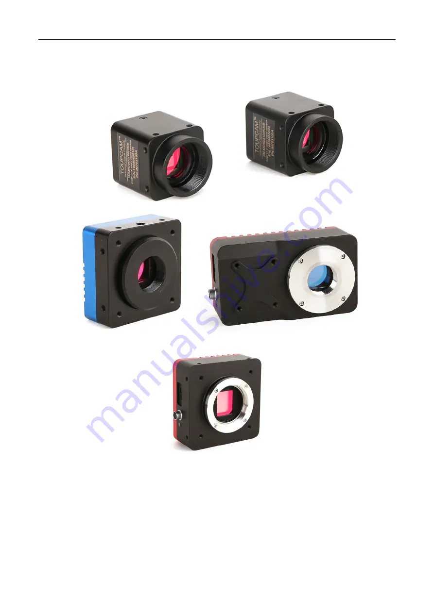
Page 82: ...on Cameras 81 8 5 I3CMOS and I3ISPM series camera dimensions and outputs 8 5 1 I3CMOS and I3ISPM series camera mechanical housing dimensions Figure 8 14 I3CMOS or I3ISPM series camera Figure 8 15 Dime...

Page 83: ...ound blue 3 OPTO_OUT Opto isolated output signal line1 green 4 OPTO_IN Opto isolated input signal line0 black 5 GND Direct coupled signal ground yellow 6 DIR_OUT Direct coupled output signal line3 Tab...

Page 84: ...User Manual for Machine Vision Cameras 83 3 USB3 0 cable 1 Suitable length of Micro USB3 0 cable 4 Lens optional 1 C mount lens Table 8 9 Packing information and recommended accessories...

Page 85: ...piled by toolchain aarch64 linux gnu version 4 9 2 Android arm arm64 x86 x64 Compiled by android ndk r18b 9 1 2 SDK content brief introduction ToupCam series cameras support a variety of API including...

Page 86: ...Pull Mode mechanism In order to keep the code clean the WTL library used by the example can be downloaded from this link http sourceforge net projects wtl 2 demopush take C for example using the Push...

Page 87: ...t example is about 60 lines of code demoraw RAW data and static capture about 120 lines of code extras directshow DirectShow SDK and demo programs twain TWAIN SDK labview Labview SDK and demo programs...

Page 88: ...on brightness contrast gamma value adjustment feature Frame rate control According to the performance of different computers and USB the compatibility of the camera can be realized by adjusting the fr...

Page 89: ...counting The segmentation and counting of ToupView provides six image segmentation methods for users to call according to different image characteristics The six segmentation methods are watershed dar...

Page 90: ...on fails the camera will not be found by the client software After the installation is complete in the Device Manager you can see the new device type such as I3CMS05000KMB and then right click the mou...

Page 91: ...User Manual for Machine Vision Cameras 90 Figure 10 3 democpp UI...

Page 92: ...sition and resolution The following is the API code for the image capture operation still image snap Toupcam_Snap HToupCam h unsigned nResolutionIndex multiple still image snap Toupcam_SnapN HToupCam...

Page 93: ...32 RGB48 IUA1700KMA Y Y Y Y Y Y IUA1700KPA Y Y Y Y Y Y IUA2100KPA Y Y Y Y Y Y IUA2300KMB Y Y Y Y Y Y IUA2300KPB Y Y Y Y Y Y IUA4100KPA Y Y Y Y Y Y IUA6300KMA Y Y Y Y Y Y IUA6300KPA Y Y Y Y Y Y IUA7100...

Page 94: ...peed HToupCam h unsigned short nSpeed 11 2 3 Area of interest setup When the user is only interested in some details of the image the camera can output the image ROI according to the requirement Setup...

Page 95: ...yOffset unsigned xWidth unsigned yHeight 11 3 Global Shutter and Rolling Shutter 11 3 1 Global Shutter For cameras that support global shutter exposure starts in each line simultaneously After the ex...

Page 96: ...ing are the API codes for the switching of the free run mode to trigger mode 0 video mode 1 software or simulated trigger mode 2 external trigger mode Toupcam_put_Option m_hCam TOUPCAM_OPTION_TRIGGER...

Page 97: ...ll send the command through USB3 0 to activate the camera to acquire and transmit images As shown in Figure 11 7 in democpp first click Enter Trigger Mode to enter trigger mode Click Set trigger Numbe...

Page 98: ...The trigger source is selected in the Trigger Source and then click OK At this time a high pulse will trigger the camera on the corresponding line Figure 11 9 I O control dialog 11 4 4 Frame burst mod...

Page 99: ...hree trigger signals before it can begin exposure as shown in Figure 11 11 Trigger exposure Sensor exposure1 Sensor exposure2 Trigger delay Trigger delay Figure 11 11 Counter trigger mode The specific...

Page 100: ...trigger pulse width as shown in Figure 11 13 Trigger_in1 Trigger_in2 Trigger_in3 Sensor exposure1 Sensor exposure2 Sensor exposure3 Debounce time Debounce time Debounce time t1 t1 t2 t2 t3 t3 Figure...

Page 101: ...6 Input signal 11 6 1 Signal debouncer Because the external trigger input signal of the camera may have burr if it goes directly into the internal logic of the camera it will cause false trigger The i...

Page 102: ...the output signal Figure 11 18 Output signal mode setup The following is the API code for the setup of the output signal mode Toupcam_IoControl m_hCam index TOUPCAM_IOCONTROLTYPE_SET_OUTPUTMODE val N...

Page 103: ...nd set the time in Strobe Delay Time Strobe Duration can set the effective level duration of Strobe Figure 11 20 Strobe settings The following is the API code for the setup of the output Strobe signal...

Page 104: ...hown in Figure 11 22 Figure 11 22 Strobe output delay Strobe Pre output The camera also provides a pre output feature of the strobe signal that is the strobe signal takes effect earlier than the expos...

Page 105: ..._IOCONTROLTYPE_SET_OUTPUTMODE 3 NULL Toupcam_IoControl m_hCam 0 TOUPCAM_IOCONTROLTYPE_SET_USERVALUE val NULL 11 8 Camera control parameter configuration 11 8 1 Exposure time The exposure time range is...

Page 106: ...at different color temperatures by adjusting the R B component s gain on the image Ideally the ratio of R G and B components in the white region is 1 1 1 The white balance setting is shown in Figure 1...

Page 107: ...put_HFlip HToupCam h int bHFlip horizontal flip Figure 11 27 Image flip setup 11 8 6 Test pattern In democpp as shown in Figure 11 28 clicking Action in the control menu then clicking Test Pattern sel...

Page 108: ...User Manual for Machine Vision Cameras 107 Figure 11 29 Grayscale gradient oblique stripes Figure 11 30 Grayscale gradient vertical stripes Figure 11 31 Grayscale gradient horizontal stripes...

Page 109: ...isolated input circuit line0 In the camera I O control opto isolated input circuit is shown in Figure 11 32 Figure 11 32 Opto isolated input circuit Logic 0 input level 0 1 4VDC OPTO_IN pin Logic 1 in...

Page 110: ...delay TDR 17 5us Output drop delay TDF 4 2us Table 11 3 Opto isolated output signal s electrical characteristics The corresponding current and output logic low level parameters are shown in Table 11...

Page 111: ...output level parameter The maximum current allowed through this pin is 25 mA When the ambient temperature is 25 degrees Celsius the relationships between the external voltage resistance and output low...

Page 112: ...3 series camera s configurable input and output I O circuits line2 Camera with hardware version V2 0 and above its input and output I O circuits are shown in Figure 11 39 Figure 11 39 Non isolated con...

Page 113: ...and output low level are shown in Table 11 7 Externalvoltage Non essentialresistance VL GPIO 3 3V 1K 0 11V 5V 1K 0 167V 12V 2 4K 0 184V 24V 4 7K 0 385V Table 11 7 Non isolated output logic low level...

Page 114: ...level 0 2 2VDC OPTO_IN pin Logic 1 input level 3 3 24VDC OPTO_IN pin Maximum input current 30mA The input level is between 2 2V and 3 2V the circuit action state is uncertain please avoid the input v...

Page 115: ...ay TDR 12us Output drop delay TDF 2us Table 11 9 Opto isolated output signal s electrical characteristics The corresponding current and output logic low level parameters are shown in Table 11 10 when...

Page 116: ...onfigurable input output I O circuit line3 1 Line2 line3 set as input pin Logic 0 input level 0 0 6 VDC DIR_GPIO1 DIR_GPIO2 pin Logic 1 input level 2 0 24VDC DIR_GPIO1 DIR_GPIO2 pin Maximum input curr...

Page 117: ...and output low level are shown in Table 11 11 Externalvoltage Non essentialresistance VL GPIO 3 3V 1K 0 11V 5V 1K 0 167V 12V 2 4K 0 184V 24V 4 7K 0 385V Table 11 11 Non isolated output logic s low le...

Page 118: ...117 The I3 series industrial camera can use the updatefw exe tool available in the SDK for firmware field upgrades For the latest version of the firmware xxxxx ufw file please contact technical suppo...

Page 119: ...s to determine the following three parameters Trigger Delay Debouncer Time and Strobe Delay Time As shown in Figure 12 1 the trigger signal is first subjected to a debounce delay and then a trigger de...

Page 120: ...02 2019 04 02 Initial release 2 1 0 20190614 2019 06 14 Add 0 5M pixel camera related content Add the relevant content of the camera with hardware version number V2 0 and above Add Sec 4 4 to the GPIO...

Page 121: ...14 Support You can also get support in the following ways Web site support http www touptek com for relevant documentation and on line technical support E mail support support touptek com Other suppo...

Reviews: