User Manual for Machine Vision Cameras
76
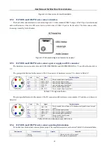
Figure 8
-
5
Schematic diagram of IUA camera back panel
8.2.3
IUA series camera power supply and I/O connector
The pin signal definition for the IUA series camera 7 Pin I/O connector is shown in Table 8
Color
Pin
Signal
Signal description
White
1
GND
Direct
-
coupled signal ground
Red
2
5V
5VDC power input or output
Blue
3
OPTO_GND
Opto
-
isolated signal ground
Yellow
4
DIR_GPIO1
Direct
-
coupled General Purpose I/O (Software configurable input/output) (line2)
Black
5
DIR_GPIO2
Direct
-
coupled General Purpose I/O (Software configurable input/output) (line3)
Green
6
OPTO_IN
Opto
-
isolated input signal (line0)
Pink
7
OPTO_OUT
Opto
-
isolated output signal (line1)
Table 8
-
1 IUA series pin signal definition
8.2.4
IUA series camera packing information
For normal use of industrial cameras, please prepare the required accessories as shown in Table 8
2 before installation.
Order number
Accessories name
Quantity
Instruction
1
Camera
1
Camera referred in this manual
2
I/O cable
1
7 Pin cable or extended cable
3
USB3.0 cable
1
Suitable length of Micro USB3.0 cable
4
Lens (optional)
1
C
-
mount lens
Table 8
-
2
Recommended accessories for IUA series camera


