background image

- 10 - 

tousek

  /  E_PASS-838_02  /  22. 10. 2018

5.

  Attachment  


of warning signs 

•  Additionaly to the safety installations of the barrier as 

suggested by safety instructions in effect, some warning 

signs have to be installed to warn pedestrians, bicycle 

drivers etc. showing special attention and informing 

of possible danger and for guidance to an alternative  

route.


ATTENTION

A U T O M

A T I C   B

A R R I E R

RELEASE

LOCKING

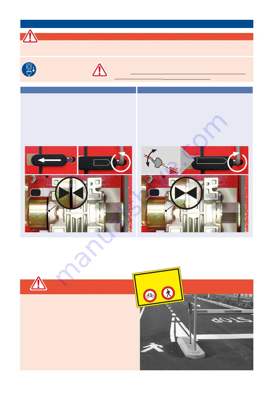
•  Open the housing door and slide the cover of the emergency 

release in direction of front part of housing.

•  Insert the 10mm Allan Key and turn it 2–3 times counter 

clockwise. This disengages the gear lever 

(G)

 from the 

gearing transmission.

 •  The operator is now unlocked and the boom may be moved 

manually 

(slowly ! - not faster than with the operator).

•  To restore operation of the motor pull the emergency release 

clockwise again firmly.

  Move the boom a little so that the lever gear snaps into the 

gearing.

•  The lever gear 

(G)

  must rest again directly on the gearing 

unit.

•  After closing the housing door and turning on the power 

supply, the motorised mode can be engaged again.

2–3x

Release

G

Locking

tighten

+

G


Acute risk of injury

The operator may only be emergency released if:

>>>  the power supply is turned off and >>> the barrier boom is mounted

•  Turn off power supply 

of gate facility!

•  ATTENTION: Make sure that the barrier boom is mounted!

• 

If the barrier boom is removed, there is no counterweight to the spring 

tension.

 In this case the operator may not be emergency released 

since this could lead to 

SERIOUS INJURIES !

4. 

Emergency release of the operator at power failure  

PASS 838

Summary of Contents for Pass 838

Page 1: ...Installation and operating manual Barrier PASS 838...

Page 2: ...ontact opening gap of minimum 3 mm has to be foreseen When installing the safety device photocells safety edges emergency stops etc please comply with the valid direcitves standards the criteria of pr...

Page 3: ...boom can be opened and closed manually after loosening the emergency release hand wheel Due to its particularly massive execution and the very short opening and closing times the Tousek PASS 838 barr...

Page 4: ...ng lever 3 chain 4 gearing lever 5 balancing spring 6 euro standard lock cylinder 7 earthing bolt 8 activator bolt for door switch 9 door safety switch 10 drive shaft 11 Limit bolt boom OPEN 12 Limit...

Page 5: ...he barrier where you wish to mount the boom The following mounting steps differ in accordance of whether you wish to mount the round or the flat barrier boom Important grease the drive shaft put some...

Page 6: ...40 and disc with drive shaft A close the opening of boom with plastic plug Attach the plastic covers onto the boom and drive shaft end Fixing the flat boom example as left barrier M housing backside e...

Page 7: ...with the boom Then bolt 4 x with discs the boom carrier M with the slide in module inside boom E Now connect the boom B with cylinder head bolt M10 x 40 and disc with drive shaft A close the opening...

Page 8: ...An all pole disconnecting mains switch with a contact opening gap of min 3 mm has to be foreseen The gate facility has to be secured according to the valid safety regulations IMPORTANT The control li...

Page 9: ...or The switching time and also the boom limit positions can be defined by bolting in or out the limit stop bolts Note Please note that when the limit stop bolts are being adjusted AO or AG the limit p...

Page 10: ...may be moved manually slowly not faster than with the operator Torestoreoperationofthemotorpulltheemergencyrelease clockwise again firmly Move the boom a little so that the lever gear snaps into the...

Page 11: ...laws during installation or operation of the gate facility Note concerning cable laying The electric cables have to be laid in insulating sleeves whicharesuitableforundergroundusage Theinsulating slee...

Page 12: ...with the grease press Check and adjust the end positions opened and closed Check the proper function of the emergency release Check the proper function of the housing lid safety switch Check the gear...

Page 13: ...om the ground level to a minimum of 100mm Thefoundationdepthfromgroundleveltoshould have a minimum of 800mm frost resistant The foundation always has to be adjusted to the structure of the ground It s...

Page 14: ...ons subject to change 280 250 280 290 180 180 255 290 30 135 3 950 1100 116 100 100 base plate barrier width boom length NOTE 838V ST 838 L3 ST80 838 L4 ST80 838 L6 ST80 max barrier width 3m 4 5m 6m b...

Page 15: ...do a una razonada solicitud dentro de un plazo razonable en forma electr nica Para la preparaci n de la documentaci n t cnica est autorizada TOUSEK Ges m b H A1230 Viena Zetschegasse 1 Austria La m qu...

Page 16: ...ka 67 Tel 48 32 738 53 65 Fax 48 32 738 53 66 info tousek pl Tousek s r o Czech Republic CZ 130 00 Praha 3 Jagellonsk 9 Tel 420 2 2209 0980 Fax 420 2 2209 0989 info tousek cz We reserve the right to c...

Reviews: