background image

tousek

  /  E_PASS-838_02  /  22. 10. 2018 

- 13 -

V

120
150

Ø30

190

(L6: 220)

290

255

180

290

180

Foundation plate 

PASS 838

Foundation plate 

Tip rest/support fork

40

80

390

330

210

3000

120
150

Ø30

190

(L6: 220)

290

255

180

290

180

Foundation plate 

PASS 838

Foundation plate 

Tip rest/support fork

40 80

390 330

210

3000

Foundation  plate  

Impulse pillar V03

Foundation plate 

Impulse column V03

Distance depending 

on road width

Distance depending 

on road width

V

2

2

1

1

5

5

100

100

100

100

Ø70

Ø70

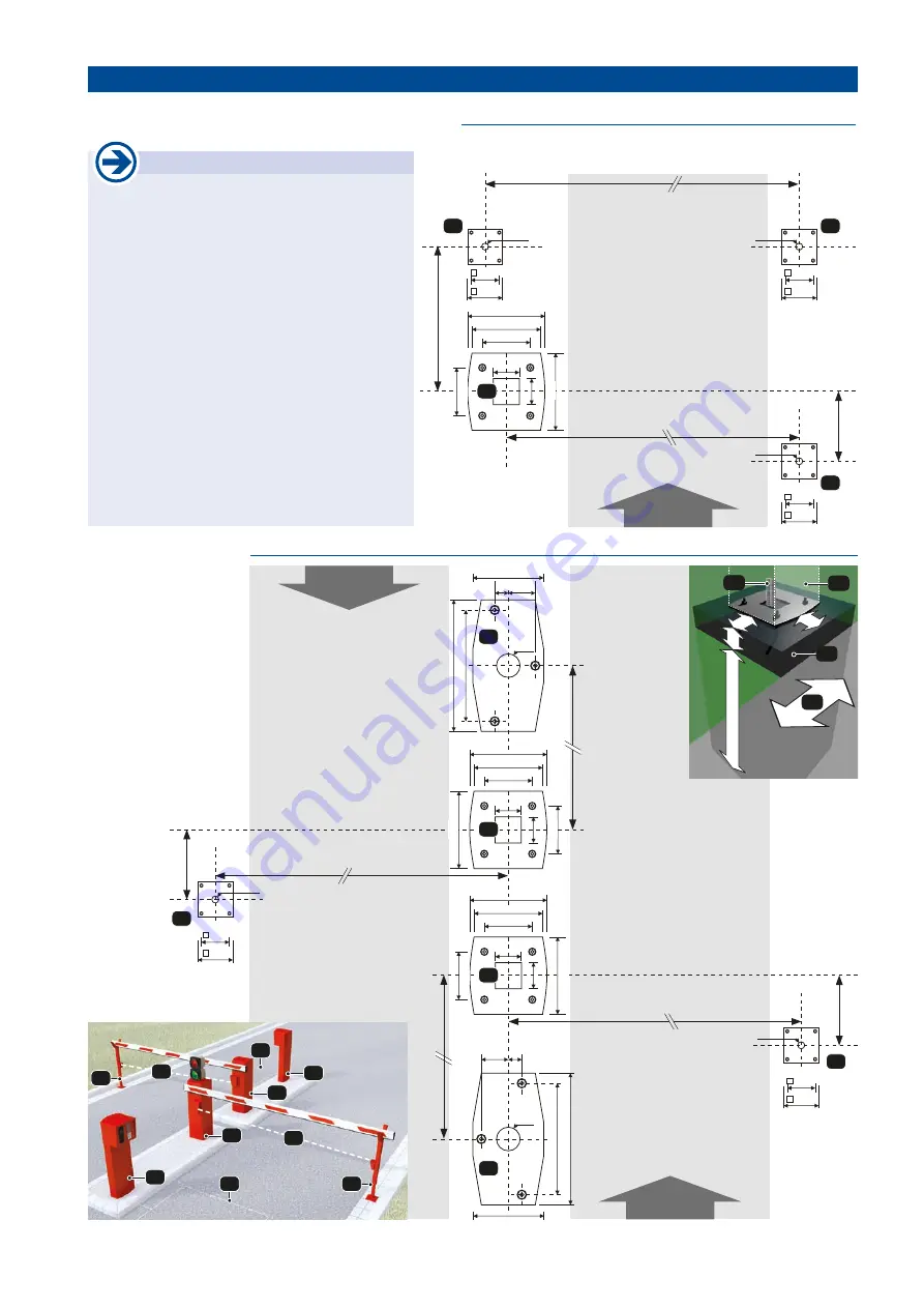
8.  Barrier installations - Examples  

Barrier PASS 838

•  Dimensions in mm

2

2

1

1

3

3

4

4

5

5

(1)

 Barriers PASS 838

(2)

 Impulse 

columns

(3)

 Photocells

(4)

 Induction loops

(5)

 Tip rests/support forks

(6)

 Photocell pillars

 Important

•  The foundations to be made must be at least 

100mm 

larger around then the foundation plates 

concerned.  

•  The foundation must be raised from the ground 

level to a minimum of 

100mm.


•  The foundation depth from ground level to should 

have 

a minimum of 800mm

 (frost resistant).

•  The foundation always has to be adjusted to the 

structure of the ground.


It should consist of concrete quality C20/25 

at ground class 3. The foundation has to be 

horizontal and free of cracks.

•  When using a support fork/tip rest pay attention 

to the offset 

V,

 which depends on the barrier 

used (barrier boom):


For barriers with flat boom: 

V = 190


For barrier type PASS 838 L6  

(= barrier with round boom): 

V = 220

Single barrier with support fork and photocell pillars

Barrier system for separate entrance / exit with impulse columns V03

1

5

6

6

V

120
150

Ø30

190

(L6: 220)

290

255

180

290

180

Foundation plate 

PASS 838

Foundation plate 

Tip rest/support fork

390

Foundation plate 

Photocell pillar

Foundation  plate  

Photocell pillar

120
150

120
150

Distance depending on road width

Distance depending 

on road width

Ø30

Ø30

100

100

1

(F)

 foundation

(S)

  insulating sleeves

(T)

  housing door

(FB)

 road

100

800

100

100

FB

T

S

F

Summary of Contents for Pass 838

Page 1: ...Installation and operating manual Barrier PASS 838...

Page 2: ...ontact opening gap of minimum 3 mm has to be foreseen When installing the safety device photocells safety edges emergency stops etc please comply with the valid direcitves standards the criteria of pr...

Page 3: ...boom can be opened and closed manually after loosening the emergency release hand wheel Due to its particularly massive execution and the very short opening and closing times the Tousek PASS 838 barr...

Page 4: ...ng lever 3 chain 4 gearing lever 5 balancing spring 6 euro standard lock cylinder 7 earthing bolt 8 activator bolt for door switch 9 door safety switch 10 drive shaft 11 Limit bolt boom OPEN 12 Limit...

Page 5: ...he barrier where you wish to mount the boom The following mounting steps differ in accordance of whether you wish to mount the round or the flat barrier boom Important grease the drive shaft put some...

Page 6: ...40 and disc with drive shaft A close the opening of boom with plastic plug Attach the plastic covers onto the boom and drive shaft end Fixing the flat boom example as left barrier M housing backside e...

Page 7: ...with the boom Then bolt 4 x with discs the boom carrier M with the slide in module inside boom E Now connect the boom B with cylinder head bolt M10 x 40 and disc with drive shaft A close the opening...

Page 8: ...An all pole disconnecting mains switch with a contact opening gap of min 3 mm has to be foreseen The gate facility has to be secured according to the valid safety regulations IMPORTANT The control li...

Page 9: ...or The switching time and also the boom limit positions can be defined by bolting in or out the limit stop bolts Note Please note that when the limit stop bolts are being adjusted AO or AG the limit p...

Page 10: ...may be moved manually slowly not faster than with the operator Torestoreoperationofthemotorpulltheemergencyrelease clockwise again firmly Move the boom a little so that the lever gear snaps into the...

Page 11: ...laws during installation or operation of the gate facility Note concerning cable laying The electric cables have to be laid in insulating sleeves whicharesuitableforundergroundusage Theinsulating slee...

Page 12: ...with the grease press Check and adjust the end positions opened and closed Check the proper function of the emergency release Check the proper function of the housing lid safety switch Check the gear...

Page 13: ...om the ground level to a minimum of 100mm Thefoundationdepthfromgroundleveltoshould have a minimum of 800mm frost resistant The foundation always has to be adjusted to the structure of the ground It s...

Page 14: ...ons subject to change 280 250 280 290 180 180 255 290 30 135 3 950 1100 116 100 100 base plate barrier width boom length NOTE 838V ST 838 L3 ST80 838 L4 ST80 838 L6 ST80 max barrier width 3m 4 5m 6m b...

Page 15: ...do a una razonada solicitud dentro de un plazo razonable en forma electr nica Para la preparaci n de la documentaci n t cnica est autorizada TOUSEK Ges m b H A1230 Viena Zetschegasse 1 Austria La m qu...

Page 16: ...ka 67 Tel 48 32 738 53 65 Fax 48 32 738 53 66 info tousek pl Tousek s r o Czech Republic CZ 130 00 Praha 3 Jagellonsk 9 Tel 420 2 2209 0980 Fax 420 2 2209 0989 info tousek cz We reserve the right to c...

Reviews:

Related manuals for Pass 838