tousek
/ EN_REX-Force_01 / 25. 03. 2020
- 33 -
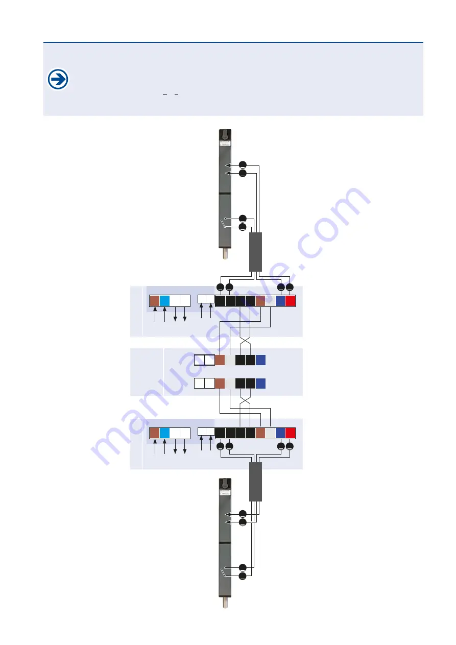
Wire the terminal block
(K)
of the dropbolt´s printed circuit board as shown on the picture::
on one hand wire it with the module, which is connected to the operator´s control unit:
- for 1 dropbolt: wire only with the terminal block „X“ - for 2 dropbolts wire with terminal blocks „X“+“Y“
on the other hand wire it with the dropbolt via connection cable 4 x 0,75
2
(motor connection and limit switch) .
Strictly note the numbering
1 – 4
of the connection cable´s wires for a proper connection.
Carry out the 230V a.c. power supply connection on terminal block
(V)
and the earthing connection on the earthing screw.
DROPBOLT 1
DROPBOLT 2
motor print 2
pre-wired
motor print 1
pre-wired
dropbolt
module
(install in control unit
ST
REX
)
3 4 4 3 1
2
M– M+
L N
5 6
Y/+ Y/-
Y/1
Y/2
Y/3Y/4Y/5
X/+ X/-
X/1
X/2
X/3X/4X/5
230V
a.c.
L N
Trafo1
primary
Trafo1
second.
3 4 4 3 1
2
M– M+
L N
5 6
230V
a.c.
L N
Trafo2
primary
Trafo2
second.
3 4
2 1
3 4
2 1
3
4
2
1
cable 4x0,75
2
3
4
2
1
cable 4x0,75
2
Limit switch closed,
if the bolt is retracted
motor
connection
Limit switch closed,
if the bolt is retracted
„X“-block“
„Y“-block
motor
connection
Connection


