17
❏
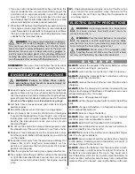
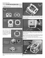
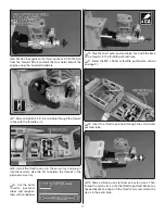
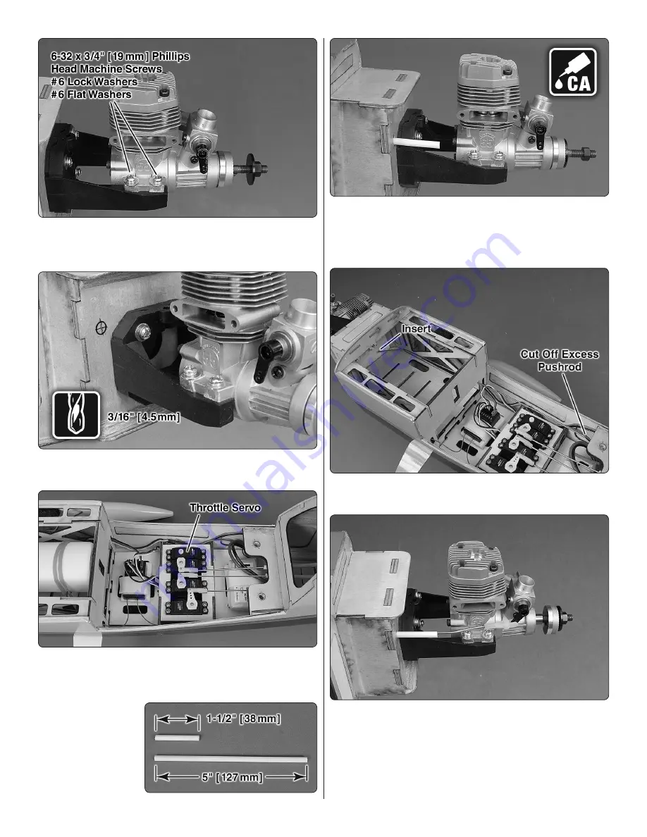
6. Position the engine so the thrust washer is 5-1/8"(130mm)
from the fi rewall. Mark and drill the four holes.Mount the
engine using the included hardware.
❏
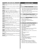
7. Mark and drill a 3/16" (4.5mm) hole through the fi rewall
in line with the throttle arm.
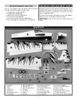
❏
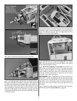
8. Install the throttle servo in the servo tray and plug it
into the receiver. Use thin CA to harden the threads in the
plywood servo tray.
❏
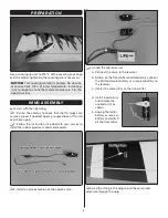
9. Cut the outer
throt tle pushrod
tubes and roughen
them with sandpaper.
❏
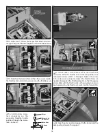
10. Glue the short outer pushrod tube, fl ush with the back
of the fi rewall, in the throttle pushrod hole.
❏
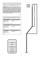
11. Bend the M2 x 500 mm throttle pushrod as shown
on page 27.
❏
12. Insert the throttle pushrod through the small outer
pushrod tube.
❏
13. Slide a silicone clevis retainer on a nylon clevis. Then,
thread the nylon clevis onto the throttle pushrod. Make any
needed bends to align with the throttle arm and attach the
clevis in the outer hole.

