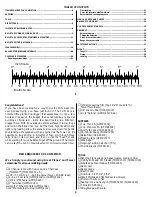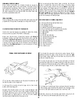
REPAIRING SURFACE DINGS
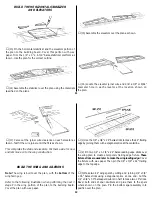
Many surface blemishes on a framed model are caused by
bumps and balsa chips on the work surface. This type of ding is
best repaired by applying a drop or two of window cleaner or
tap water to the blemish, then running a hot sealing iron over
the spot to expand the wood fibers. After the surface has dried,
sand the
expanded area smooth.
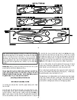
FINAL SANDING
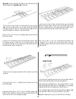
Fill any large scuffs or dings. Then sand the entire structure with
progressively finer grades of sandpaper, ending with 320-grit.
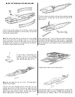
COVER THE STRUCTURE WITH TOWERKOTE
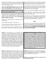
The Fun 51 does not require any painting to obtain the scheme
shown on the box, as all of the finish is MonoKote.
Make sure the structure is smoothly sanded with 320-grit
sandpaper. Remove all dust from the structure with a vacuum
cleaner and Top Flite
®
Tack Cloth so the covering will stick well.
Cover the aircraft using the sequence that follows. Make sure the
covering is thoroughly stuck to the structure and all edges are
sealed. Use a Top Flite Hot Sock
™
on your covering iron to avoid
scratching the finish.
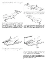
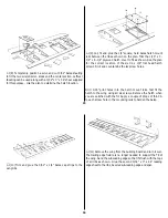
When covering areas that involve sharp junctions, like the tail
section or around the root end of the wing, cut narrow strips
(1/4" to 3/8") and apply them in the corners before covering the
major surfaces. The larger pieces of covering will overlap and
capture these smaller pieces. This technique also bypasses the
need to cut the covering in these areas after it has been applied.
DO NOT, under any circumstances, attempt to cut the covering
material after it has been applied to the fin and stab, except
around the leading and trailing edges.
RECOMMENDED COVERING SEQUENCE
❍
1. Tail junction strips as described above
❍
2. Wing/fuse junction
❍
3. TE surfaces of wing
❍
4. Bottom of left and right wing panels
❍
5. Top of left and right wing panel and wing tips
❍
6. Fuse sides (overlap at top and bottom)
❍
7. Stab bottom
❍
8. Stab top
❍
9. Fin left and right side
❍
10. Rudder left and right side
❍
11. Bottom of elevators
❍
12. Top of elevators
❍
13. Ends of ailerons
❍
14. Bottom of ailerons
❍
15. Top of ailerons
❍
16. Hatch cover
21
FINAL HOOKUPS AND CHECKS
❍
(1) Lay the control surfaces over the plans for reference and
mark the location of the hinge slots.
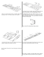
Cut through the covering at each hinge slot on the control
surface and its mating part.
Roughen the elevator joiner wire with coarse sandpaper. Pack
30-minute epoxy into the holes in the elevator halves with a
toothpick. Insert the joiner wire into both elevators and place
the assembly on a flat surface to cure. Be sure the elevator
leading edge is straight before the epoxy cures.
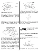
❍
(2) Install the elevator and ailerons using hinges. When
satisfied with the fit, place a few drops of CA glue into both
sides of each hinge. After the CA has cured, move each control
surface to loosen them up.
Put a dab of petroleum jelly on the top and bottom of the tail
gear bracket where the wire passed through it. Pack the hole in
the rudder with 30-minute epoxy, Then, fit the rudder in position
with hinges. Apply thin CA to both sides of each hinge.
❍
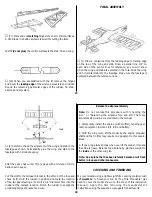
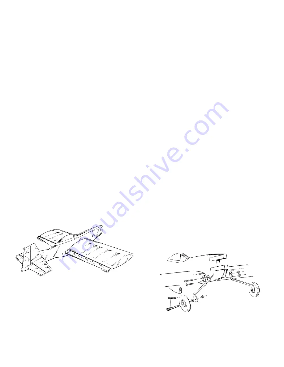
(3) Poke two holes through the covering at the bolt locations
for the landing gear struts. Bolt the struts to the fuselage, using
two 6-32 x 3/4" pan head screws and two 6-32 lock nuts.
Install the wheels on the landing gear struts using two 8-32
x 1-1/4" bolts, two #8 flat washers and four hex nuts.
22


