❍
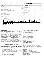
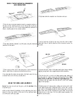
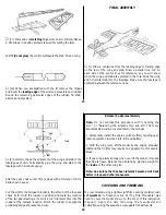
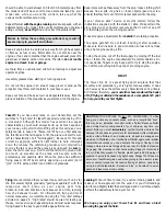
(4) Assemble your 4 or 6 oz. fuel tank.
Open the three “closed loop” screw eyes to make hooks as
shown. Locate the position of the hooks and screw them into the
fuselage. Place a piece of 1/4" foam between the fuselage side and
the tank and rubber band the tank in place as shown. You may
want to use three rubber bands to secure the tank to the aircraft.
❍
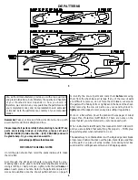
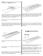
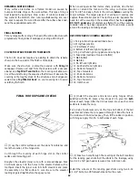
(5) Install a spinner on your engine. Position the engine so the
back edge of the spinner is approximately 3/32" in front of the
fuselage. Mark the location of the engine mounting holes.
❍
(6) Drill four 1/8" holes through the ply engine mounts. Use
two #6 washers between the engine and the mounts under the
two front holes. This will provide the required 2 degrees of right
thrust. Secure the engine with four 4-40 x 1" pan head bolts,
lock nuts and washers.
❍
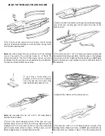
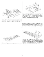
(7) Install all five control horns. Drill the required 3/32" holes,
using a control horn as a locating template. Secure the horns with
two 2-56 x 5/8" machine screws. Trim off the excess threaded
portion of the screws after tightening.
23
❍
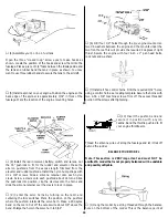
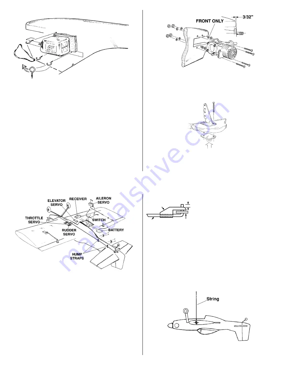
(8) Install the radio receiver, battery, switch and servos. Cut
the 35" pushrods to fit for the rudder and elevator. Make the
aileron pushrods from the excess length trimmed from the
elevator and rudder pushrods. Install the nylon hump straps with
#2 x 3/8" screws. Slide a silicone retainer onto each nylon
clevis. Screw a clevis onto each pushrod about 14 turns. Slide
the pushrods into position, clip the clevises onto the horns and
slide the silicone retainer over the clevis to lock in place.
❍
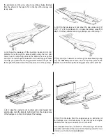
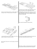
(9) Center the servo horns by turning on the radio and
centering the trim switches. Mark the position on the pushrod
where the pushrod intersects the servo horn. Make a 90 degree
bend on the mark. Cut off the excess wire about 3/8" above the
bend. Enlarge the hole in the servo horn to 5/64".
❍
(10) Insert the pushrod end and
secure it in position with a nylon
Faslink. Bend the throttle pushrod to fit
your engine throttle arm.
Thread the antenna wire out along the fuselage and let it trail off
behind the rudder.
BALANCE YOUR MODEL
Note: This section is VERY important and must NOT be
omitted! A model that is not properly balanced will be unstable
and possibly unflyable.
❍
(1) Hang the model by a string threaded through the balance
hole on the bottom of the model. This is the balance point at
FasLink
1/16"
2-56 (.074")
Pushrod Wire
Servo Horn
24


