background image

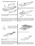
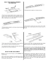
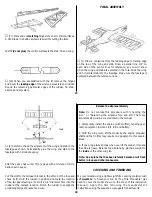
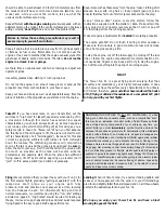
(12) Cut, fit and glue the 3/32" x 3" balsa wing center

sheeting and 3/32" x 1/4" balsa cap strips to the wing ribs.

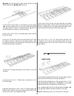
(13) Sand the top and bottom leading edge sheeting until it is

flush with the front face of the sub-leading edge, as shown. 

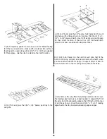
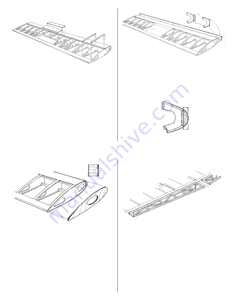
Diagonally splice, at the wing centerline, the two 1/4" x 1-1/8" 
x 24" balsa leading edge pieces. 

You used these pieces as a

trailing edge fixture earlier in the wing construction. Glue them
to the the sub-leading edge

Carve and sand the leading edge to shape as shown.

17

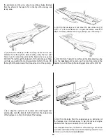
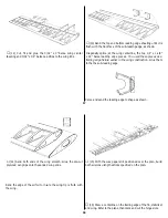
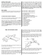
(14) Sand both ends of the wing smooth. Glue the die-cut

plywood wing tips onto the sanded wing ends.

Sand the edge of the airfoil to insure the wing tip is flush with
the wing.

(15) With the wax paper still positioned over the plan, build

both ailerons using the sticks specified on the plan.

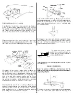
(16) Draw a centerline on the trailing edge of the fin, stabilizer

and wing. Refer to the plans, then mark and cut the hinge slots. 

18

Summary of Contents for FUN 51

Page 1: ...e user accepts all resulting liability If the buyers are not prepared to accept the liability associated with the use of this product they are advised to return this kit immediately in new and unused condition to Tower Hobbies The Fun 51 is not a toy but rather a sophisticated working model that functions very much like an actual airplane Because of its performance the Fun 51 if not assembled and ...

Page 2: ...ls covering film Top Flite MonoKote or Tower TowerKote 1 4 Foam rubber HCAQ1000 2 1 4 Spinner GPMQ4517 Red SUPPLIES 1 oz Thin CA GPMR6002 1 oz Medium CA GPMR6008 6 minute epoxy TOWR3300 30 minute epoxy TOWR3350 Balsa filler HCAR3401 Masking tape GPMR1010 Wax paper Isopropyl rubbing alcohol 70 Microballoons TOPR1090 TOOLS Sanding block and sand paper coarse medium fine Hobby knife and 11 blades TOW...

Page 3: ... parts with a hobby knife or lightly sand the back of the sheet After removing the die cut parts use your sanding block to lightly sand the edges to remove any die cutting irregularities Work on a flat surface Cover the plans with wax paper or Great Planes Plan Protectors GPMR6167 There are notes on the plans that tell you what material to use to make each part When instructed to test fit parts th...

Page 4: ...k the area on the fuselage core as shown When installing the side sheeting do NOT apply glue to the areas you just marked Be sure to mark both sides of the assembly 7 4 Using a hump strap as a template drill four 1 16 diameter holes through the two hump strap pads Set these pads aside for now Note Use only one of the six 1 4 x 3 8 x 36 balsa sticks to build the fin and rudder 5 Pin the entire fuse...

Page 5: ... not glue the marked areas from step 3 Trim the perimeter and wing opening as you did in step 7 10 Drill 1 16 diameter holes through the balsa sheeting using only the rear two pilot holes in each hump strap pad and the balance hole Drill through the landing gear holes with a 5 32 bit 9 11 Using the engine mount doublers and a landing gear strut as templates mark the balsa to be trimmed from the un...

Page 6: ... AND AILERONS Note The wing is built over the plan with the bottom of the wing facing up Refer to the following illustration when performing the next 3 steps Pin the wing portion of the plan to the building board Cover the plan with wax paper 1 Use the 1 8 x 3 8 x 24 balsa sticks to make the 44 trailing edge by joining them with a diagonal splice at the centerline 2 Pin two 1 4 x 1 1 8 x 24 balsa ...

Page 7: ...ng rails into the square holes in the proper ribs Splice two 3 32 x 7 8 x 24 balsa sheets together with a diagonal cut to make the sub leading edge Glue the sub leading edge to the front of all 2 ribs and to the leading edge doubler 13 6 Glue the top spar assembly into the notches in all of the wing ribs Cut and glue the 1 16 x 3 balsa shear webs securely to the front of the spars Diagonally splic...

Page 8: ...hatch screws Drill and countersink the six screw holes Drill 1 16 pilot holes into the hatch mount rails Test fit the hatch to the wing using all six screws Remove the hatch when you are satisfied with the fit Apply a couple of drops of thin CA to each screw hole in the mounting rails to harden the balsa 15 10 Trim and glue the 3 32 x 1 4 balsa cap strips to the wing ribs 11 Remove the wing from t...

Page 9: ...ling edge fixture earlier in the wing construction Glue them to the the sub leading edge Carve and sand the leading edge to shape as shown 17 14 Sand both ends of the wing smooth Glue the die cut plywood wing tips onto the sanded wing ends Sand the edge of the airfoil to insure the wing tip is flush with the wing 15 With the wax paper still positioned over the plan build both ailerons using the st...

Page 10: ...nd of the fuse and check its fit Hold the rudder in position and mark the location of the tail gear steering arm Drill a 1 8 diameter hole into the rudder at the marked location Notch the rudder to accept the protruding tail gear bracket and wire COVERING AND FINISHING We recommend using a light weight film covering material such as TowerKote to finish your Fun 51 Top Flite MonoKote was used to co...

Page 11: ...except around the leading and trailing edges RECOMMENDED COVERING SEQUENCE 1 Tail junction strips as described above 2 Wing fuse junction 3 TE surfaces of wing 4 Bottom of left and right wing panels 5 Top of left and right wing panel and wing tips 6 Fuse sides overlap at top and bottom 7 Stab bottom 8 Stab top 9 Fin left and right side 10 Rudder left and right side 11 Bottom of elevators 12 Top of...

Page 12: ...and servos Cut the 35 pushrods to fit for the rudder and elevator Make the aileron pushrods from the excess length trimmed from the elevator and rudder pushrods Install the nylon hump straps with 2 x 3 8 screws Slide a silicone retainer onto each nylon clevis Screw a clevis onto each pushrod about 14 turns Slide the pushrods into position clip the clevises onto the horns and slide the silicone ret...

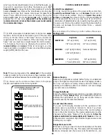
Page 13: ...13mm 7 8 down 22mm 1 2 down 13mm RUDDER 1 3 4 right 44 5mm Same as high rates 1 3 4 left 44 5mm AILERONS 1 up 25 4mm 5 8 up 16mm 1 down 25 4mm 5 8 down 16mm 25 Note Throws are measured at the widest part of the elevators rudder and ailerons If your radio does not have dual rates set the control throws halfway between the specified high and low rates 2 Make sure the control surfaces move in the pro...

Page 14: ... has excellent low speed characteristics you should always build up as much speed as your runway will permit before lifting off as this will give you a safety margin in case of a flame out When you first advance the throttle and the tail begins to lift the plane will start to turn left a characteristic of all tail draggers Be ready for this and correct by applying sufficient right rudder to hold i...

Reviews: