background image

READ THROUGH THIS MANUAL

BEFORE STARTING CONSTRUCTION.

IT CONTAINS IMPORTANT INSTRUCTIONS 

AND WARNINGS CONCERNING THE 

ASSEMBLY AND USE OF THIS MODEL.

WEIGHT

5.6 – 6.4 oz [160 –180 g]

WING LOADING

3.1– 3.5 oz/ft

2

 [9 –11 g/dm

2

]

RADIO

4 channel

To w e r 
Hobbies

®


guarantees 
this kit to be 
free from defects 
in both material and 
workmanship at the 
date of purchase. This 
warranty does not cover any 
component parts damaged by 
use or modification. In no case 
shall Tower Hobbies’ liability exceed 
the original cost of the purchased kit. 
Further, Tower Hobbies reserves the right to 
change or modify this warranty without notice.
In that Tower Hobbies has no control over the final 
assembly or material used for final assembly, no 
liability shall be assumed nor accepted for any damage 
resulting from the use by the user of the final 
user-assembled product. By the act of using the 
user-assembled product, the user accepts all resulting liability.
If the buyer is not prepared to accept the liability associated with the 
use of this product, the buyer is advised to return this kit immediately in 
new and unused condition to the place of purchase.
To make a warranty claim send the defective part or item to Hobby Services at 
the address below:
Hobby Services • 3002 N. Apollo Dr.  Suite 1 • Champaign IL  61822 • USA
Include a letter stating your name, return shipping address, as much contact information 
as possible (daytime telephone number, fax number, e-mail address), a detailed description 
of the problem and a photocopy of the purchase receipt. Upon receipt of the package the 
problem will be evaluated as quickly as possible.

WA

R

R

A

N

T

Y

TOWA2005

© 

2015 Tower Hobbies.

®

  A subsidiary of Hobbico, Inc. 

®

®

TOWER HOBBIES

Champaign, Illinois

 (217) 398-8970 ext. 5

WINGSPAN

33.5 in [850 mm]

WING AREA

261 in

2

  [16.8 dm

2

]

LENGTH

33 in [840 mm]

airsupport@hobbico.com

I N S T R U C T I O N   M A N U A L

MOTOR

RimFire

 250,

2S or 3S 350 mAh LiPo,

8A –10 A ESC, 8 x 3.8 APC Prop

Summary of Contents for Laser 200 Flatty

Page 1: ...ng the user assembled product the user accepts all resulting liability If the buyer is not prepared to accept the liability associated with the use of this product the buyer is advised to return this kit immediately in new and unused condition to the place of purchase To make a warranty claim send the defective part or item to Hobby Services at the address below Hobby Services 3002 N Apollo Dr Sui...

Page 2: ... those instances the written instructions should be considered as correct 3 You must use an R C radio system that is in good condition All components must be correctly installed so that the model operates correctly on the ground and in the air You must check the operation of the model and all components before every flight 4 If you are not an experienced pilot or have not flown this type of model ...

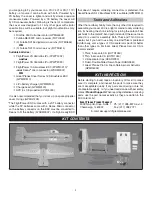
Page 3: ...If a flight ready ESC that doesn t require soldering connectors is preferred the Great Planes SS 12 Brushless ESC is suitable GPMM1810 Tools and Adhesives Other than ordinary hobby tools the only other tool required to assemble your Laser 200 is a light or medium duty soldering iron for heating the shrink tubing for joining the carbon fiber pushrods to the metal Z bend pushrod ends Otherwise foam ...

Page 4: ...to prevent the tip from splitting Simply cut off the end of the tip each time it becomes clogged until it s too short then replace it with another D Small paper towel squares cut from two or three paper towel sheets stacked on top of each other come in handy for wiping residual CA off your model as you proceed E Use care when wiping excess CA off the model you get only one or two chances before th...

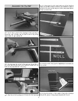
Page 5: ...he right side has just a single slot little glue is required but you do want to apply it evenly and get it all the way to the edges 5 Glue the bottom fuselage half to the wing horizontal fuselage section As you proceed use a small builder s square to make certain the fuselage side is perpendicular 6 Use medium grit sandpaper to round both ends of all the 1mm carbon fiber braces you don t need to s...

Page 6: ...erfect length 8 Start by gluing the ends of the braces to the horizontal surfaces only use just a drop of foam safe CA so it doesn t wick down through the top All the braces will be reinforced with more glue later 9 Glue the other end of the braces to the vertical part of the fuselage using a builder s square as you proceed to make sure the fuselage remains vertical 10 Test fit the landing gear an...

Page 7: ...t the model off the plastic sheet 13 Place the structure back down onto the plastic sheet Split one end of each of the the 1mm foam brace reinforcements and glue them into position where shown it s easiest to position the reinforcement then add a drop or two of thin CA followed by a quick shot of accelerator 14 After all the reinforcements have been added you can remove the assembly from the plast...

Page 8: ...the bottom and perpendicular to the wing 3 Glue the vertical fuselage post to the bottom the fuselage 4 Fit then glue the 1mm carbon fiber top horizontal stab braces into position Same as before use a builder s square to be certain the vertical stab remains vertical and perpendicular to the horizontal stab 5 Notch position then glue the round brace reinforcements into position 6 Hinge the bottom o...

Page 9: ... foam motor mount doublers into position Hook Up the Ailerons While working on the model for the next several steps it will be handy to have a couple of small boxes or something similar to support the model upside down 1 Check the fit of the pushrods in the four laser cut plastic control horns and in the extended aileron servo arm If necessary enlarge the holes to fit the pushrods a 60 04 or 1mm d...

Page 10: ...he system up with your transmitter Also make sure the trims and sub trims are centered in your transmitter programming Find the orientation on the aileron servo arm that will be neutral as shown in the illustration then cut off the unused arms 4 Use a hobby knife to enlarge the holes in the servo arm for the screws in the extended aileron servo arm then join the two with 1 5mm x 3mm Phillips screw...

Page 11: ...d ends and the aileron pushrods 9 Make a small clamp from the piece of leftover foam from the aileron servo cutout that was in the top half of the fuselage 10 Place the clamp you made in the previous step over the end of one of the ailerons and the fuselage to hold the aileron centered With the aileron servo connected to your receiver and transmitter still on add a drop or two of thin CA to the pu...

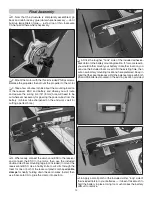
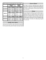
Page 12: ...guide is the front 4 Take the servo arms off the servos and connect the pushrods to the servo arms holes 1 2 13 mm out for the rudder and 3 8 10mm out for the elevator should get you the correct 3D throws with the servo end points set at 100 in your transmitter 5 Guide the pushrods down through the guides and reinstall the arms onto the servos 6 Fit the Z bend pushrod ends into the elevator and ru...

Page 13: ...or then use the included double sided foam mounting tape not included to mount the receiver and ESC Use a hobby knife to cut slits through the foam for one or both of the laser cut plastic U shaped cable clamps for neatly holding down the servo wires Install then use foam safe CA to glue the clamp into position 5 Stick the rougher hook side of the included adhesive backVelcro to the battery mounti...

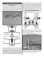
Page 14: ...n lead ballast to the nose or tail to get it to balance within the range The farther back the Laser balances the more it will float and the more responsive it will be but if it s too responsive it could be too difficult for inexperienced pilots to control The farther forward the Laser balances the more stable but the less responsive it will be Balancing the Laser within the recommended range shoul...

Page 15: ...adio control system according to the manufacturer s instructions Also be certain to set the failsafe function in your transmitter so in case of loss of signal or if you inadvertently turn off the transmitter before disconnecting the battery the motor will not run Flying The Laser 200 doesn t exhibit any unusual tendencies that you need to be made aware of ahead of time On normal rates it s a gentl...

Page 16: ......

Reviews: