10
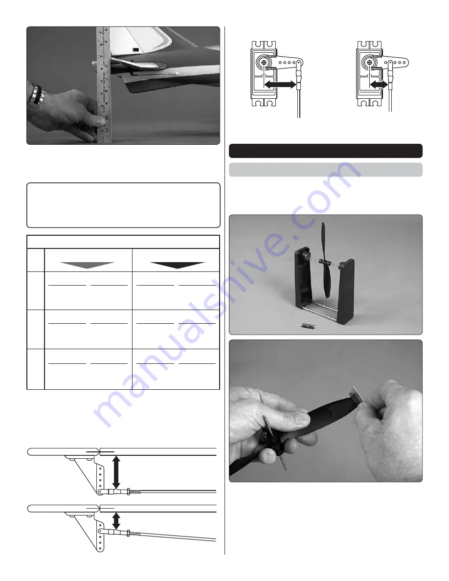
Use a ruler at the widest part (front to back) of the trailing edge
of each control surface to measure the throws, then adjust
as necessary to get the measurements in the following chart.
If your radio does not have dual rates, we recommend setting
the throws at the low rate, or between the high and low rates.
NOTE
: The throws are measured at the
widest part
of the
elevators, rudder and ailerons.
These are the recommended control surface throws:
ELEV
A
TOR
R
UDDER
AILER
ONS
LOW RATE
5/16"
[8mm] 9°
Up
1/4"
[6mm] 9°
Up
5/8"
[16mm] 13°
Right
HIGH RATE
7/16"
[11mm] 12°
Up
3/8"
[10mm] 14°
Up
1"
[25mm] 21°
Right
5/16"
[8mm] 9°
Down
1/4"
[6mm] 9°
Down
5/8"
[16mm] 13°
Left
7/16"
[11mm] 12°
Down
3/8"
[10mm] 14°
Down
1"
[25mm] 21°
Left
If you don’t get the throws specified you can use the
programming in your transmitter to adjust the servo travel, and/
or adjust the throws mechanically by changing the mounting
location of the pushrods in the servo arm and control surfaces
as shown:
Pushrod Farther Out
LESS
THROW
Pushrod Closer In
MORE
THROW
Pushrod Farther Out
MORE
THROW
Pushrod Closer In
LESS
THROW
PREFLIGHT
Balance the Propeller
An unbalanced prop can cause enough vibration to damage
parts or break glue joints. At the least, an unbalanced prop
reduces motor performance.
❏
1. Use a Top Flite
®
Precision Magnetic Prop Balancer
(TOPQ5700) to balance your propeller and spare propellers.
Use a single-edge razor blade or sandpaper to remove material
from the heavy blade until the prop balances.
❏
2. Once you have all the control throws set and are done
working on the model with your radio system turned on,
remount the propeller and spinner to the motor.


