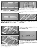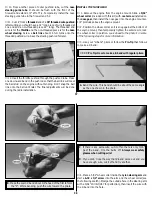
E. Use medium CA to glue the wire to the rod.
F. Cut the heat shrink into 1-1/2" lengths (four total pieces). Slide
the shrink tubing onto the rods over the wire. Leave about a
1/8" overhang off the end of the dowel. Use a heat gun or
cigarette lighter to tighten the shrink over the wire and dowel.
G. Apply thin CA inside each end of the heat shrink tubing to
complete the pushrod assembly.
❍
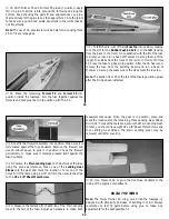
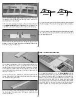
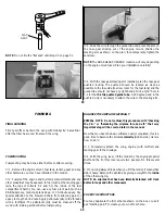
5. The Rudder and Elevator control rods need to be installed
into the fuselage from the radio compartment threaded end first.
Patience is the key to getting the rods in and having them exit in
their proper locations.
❍
6. Screw the nylon clevises well onto the ends of the pushrods
(about 14 turns). Snap the clevises onto the control horns for
now, as they will be removed later to allow bending of the wire
at the servo.
❍
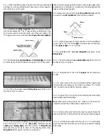
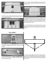
7. Cut a notch in the bottom wing skin to provide an aileron
lead exit. Use medium CA to glue the aileron servo tray (with
servo) in its place as shown on the plans.
❍
8. Hook up the nylon clevis to the nylon swivel. Thread a 12"
threaded end rod into each clevis. Screw these assemblies onto
the aileron torque rods down to the height shown on the cross
section at the centerline.
❍
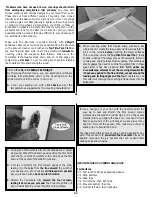
9. Mark the locations for the Z-Bends in the aileron pushrods
by holding the ailerons neutral with tape and putting marks on
the pushrods even with the holes in the servo arm. Note: When
attaching the Z-Bends to the servo arms, you’ll need to use a
5/64" drill to enlarge the holes in the servo arms. Make the
Z-Bends as shown in the following sequence
❍
10. Hook up and make final adjustments to the aileron linkage.
❍
11. Mount the wire main landing gear. Install your wheels and
tires using 5/32" wheel collars (not included) as shown on the plans.
❍
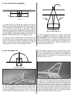
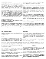
12. Locate the die-cut 1/8" plywood hatch retainer (HR).
Center the hatch retainer on the 1/8" x 4" x 5" balsa tank
compartment hatch with approximately 3/8" protruding from the
edge, then glue it in position.
47
❍
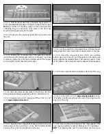
13. Position the hatch on the fuselage. Mark a cut line on the
hatch to indicate the front of the firewall. Trim the front of the hatch
to fit flush with F1A. Mark the sides of the hatch and trim it even
with the fuselage sides. Drill 1/16" holes as shown in the photo
through the hatch and into the firewall. Remove the hatch, then
enlarge the holes in the hatch only with a 3/32" drill bit.
Temporarily mount the hatch to the fuselage with #2 x 3/8" screws.
❍
14. Install the nose gear steering pushrod using the plans as a
reference. The exact installation will be dependent on your
particular selection of the pushrod.
❍
15. Install the throttle pushrod using the plans as a reference.
❍
16. Install the switch harness in the location you desire. It is
always best the switch be on the opposite side of the muffler to
prevent fuel from damaging the switch.
BALANCE YOUR MODEL
NOTE: This section is VERY important and must NOT be
omitted! A model that is not properly balanced will be unstable
and possibly unflyable.
❍
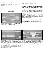
1. Use a felt tip pen or a narrow strip of tape to accurately
mark the balance point on the bottom of the wing near both sides
of the fuselage. The balance point (CG) is shown on the plan. On
the Tower Trainer 40 the (CG) is located 3-5/8" back from the
leading edge. This is the point at which your model should
balance for your first flights. Later, you may experiment by
shifting the balance up to 1/4" forward or back to change the
flying characteristics. Moving the balance forward may improve
the smoothness and arrow-like tracking, but it may require more
speed for takeoff and make it more difficult to slow down for
3-5/8"
48

